898841-UIM-B-0113

115V SYSTEMS


208-230V SYSTEMS

30 & 36 KBTU (208-230V)

INDOOR UNIT TERMINALS

INDOOR UNIT TERMINALS


SYSTEM ONLY


INDOOR UNIT TERMINALS

N(1)


2

3


N(1)

2


3


N(1)

2

3


(DATA)


(GND)


(DATA)


(GND)


(GND)


(NEUTRAL)

(DATA)


(NEUTRAL)


(NEUTRAL)


N(1)

2

3

L1

N

N(1)

2

3

L1

L2

N(1)

2

3

L1

L2


(L1)

(GND)


(L1)

(GND)


(L1)

(GND)

OUTDOOR UNIT

(NEUTRAL)

OUTDOOR UNIT


(L2)

OUTDOOR UNIT


(L2)

TERMINALS


TERMINALS


TERMINALS


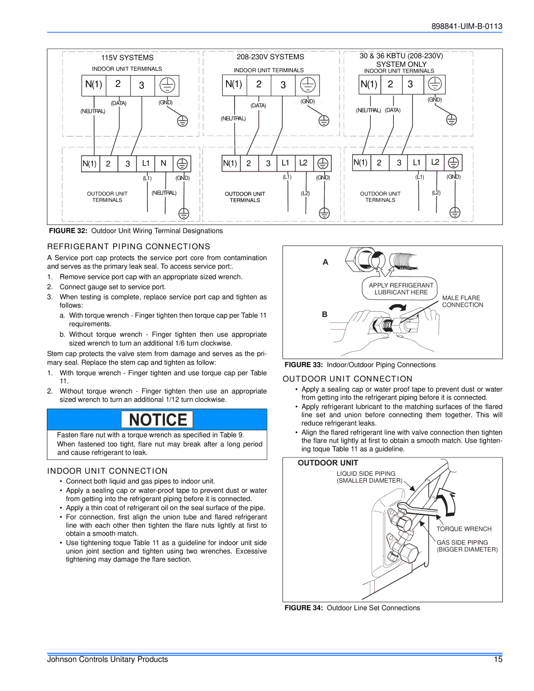
FIGURE 32: Outdoor Unit Wiring Terminal Designations

REFRIGERANT PIPING CONNECTIONS

A Service port cap protects the service port core from contamination and serves as the primary leak seal. To access service port:.

1.Remove service port cap with an appropriate sized wrench.

2.Connect gauge set to service port.

3.When testing is complete, replace service port cap and tighten as follows:

a.With torque wrench - Finger tighten then torque cap per Table 11 requirements.

b.Without torque wrench - Finger tighten then use appropriate sized wrench to turn an additional 1/6 turn clockwise.

Stem cap protects the valve stem from damage and serves as the pri- mary seal. Replace the stem cap and tighten as follow:

1.With torque wrench - Finger tighten and use torque cap per Table 11.

2.Without torque wrench - Finger tighten then use an appropriate sized wrench to turn an additional 1/12 turn clockwise.

NOTICE

Fasten flare nut with a torque wrench as specified in Table 9.

When fastened too tight, flare nut may break after a long period and cause refrigerant to leak.

INDOOR UNIT CONNECTION

Connect both liquid and gas pipes to indoor unit.

Apply a sealing cap or water-proof tape to prevent dust or water from getting into the refrigerant piping before it is connected.

Apply a thin coat of refrigerant oil on the seal surface of the pipe.

For connection, first align the union tube and flared refrigerant line with each other then tighten the flare nuts lightly at first to obtain a smooth match.

Use tightening toque Table 11 as a guideline for indoor unit side union joint section and tighten using two wrenches. Excessive tightening may damage the flare section.

A

APPLY REFRIGERANT

LUBRICANT HERE

MALE FLARE

CONNECTION

B

FIGURE 33: Indoor/Outdoor Piping Connections

OUTDOOR UNIT CONNECTION

Apply a sealing cap or water proof tape to prevent dust or water from getting into the refrigerant piping before it is connected.

Apply refrigerant lubricant to the matching surfaces of the flared line set and union before connecting them together. This will reduce refrigerant leaks.

Align the flared refrigerant line with valve connection then tighten the flare nut lightly at first to obtain a smooth match. Use tighten- ing toque Table 11 as a guideline.

OUTDOOR UNIT

LIQUID SIDE PIPING (SMALLER DIAMETER)

TORQUE WRENCH

GAS SIDE PIPING (BIGGER DIAMETER)

FIGURE 34: Outdoor Line Set Connections

Johnson Controls Unitary Products

15

Page 15
Image 15
Johnson Controls 22 SEER Refrigerant Piping Connections, Indoor Unit Connection, Outdoor Unit Connection

22 SEER specifications

Johnson Controls has long been a leader in the heating, ventilation, and air conditioning (HVAC) industry, consistently pushing the boundaries of energy efficiency and comfort. One of their standout offerings is the 22 SEER (Seasonal Energy Efficiency Ratio) air conditioning system, which boasts advanced technologies designed to deliver optimal performance while minimizing energy consumption.

At the heart of the Johnson Controls 22 SEER system is its innovative compressor technology. The variable-speed compressor allows for precise temperature control by adjusting the cooling output according to the specific demands of your space. This means that instead of constantly turning on and off, the system can operate at lower speeds for longer periods, ensuring even cooling and reducing energy bills.

In addition to the compressor, the 22 SEER unit employs high-efficiency coils and a superior refrigeration system that work in tandem to enhance performance. These components are designed to maximize heat transfer, enabling the system to cool your home more effectively and efficiently.

Another notable feature of the Johnson Controls 22 SEER system is its smart technology integration. With a focus on convenience and energy management, these units often come equipped with Wi-Fi connectivity, allowing homeowners to control their HVAC systems remotely using a smartphone app. This capability enhances user experience by enabling real-time monitoring and scheduling, ultimately leading to smarter energy use.

The design of the units also reflects an emphasis on quiet operation. Noise reduction technologies, including sound-dampening features, ensure that the system operates quietly in the background, enhancing indoor comfort without disruptive sounds.

Durability is another standout characteristic of the Johnson Controls 22 SEER systems. These units are built with high-quality materials and rigorous testing standards, ensuring they can withstand harsh weather conditions and provide reliable performance over the years.

Moreover, the 22 SEER air conditioning systems contribute to environmental sustainability. By using less energy, they not only lower utility costs but also reduce the carbon footprint of homes, aligning with growing consumer preferences for eco-friendly solutions.

Overall, the Johnson Controls 22 SEER air conditioning system represents a significant leap forward in HVAC technology. Its blend of efficiency, innovative features, and user-friendly technologies makes it an ideal choice for environmentally-conscious homeowners seeking comfort without compromise. Whether upgrading an existing system or investing in a new one, the 22 SEER unit stands out as a prime example of luxury, efficiency, and sustainability in the HVAC market.