Manuals
/
Johnson Controls
/
Household Appliance
/
Air Conditioner
Johnson Controls
J15
warranty
Models:
J15
1
36
40
40
Download
40 pages
44.97 Kb
33
34
35
36
37
38
39
40
Specification
Unit Operating Characteristics
Install
Dimension
Field-Installedaccessories
Outdoor Condenser Fan Assembly
SOUND POWER RATING1
Features
Page 36
Image 36
Page 35
Page 37
Page 36
Image 36
Page 35
Page 37
Contents
SERIES SINGLE PACKAGE GAS/ELECTRIC UNITS
AND SINGLE PACKAGE AIR CONDITIONERS
DESCRIPTION
TECHNICAL GUIDE
TABLE OF CONTENTS
LIST OF FIGURES
LIST OF TABLES
PRODUCT NOMENCLATURE
15-25Ton Series 20 Model Number Nomenclature
J15 D J N24 A 2 A AA 1 0 1 2 4 A
FEATURES
FACTORY-INSTALLEDOPTIONS
FIGURE 1 - UNIT CUTAWAY
349687-JTG-A-1007
FIELD-INSTALLEDACCESSORIES
CONTROL OPTIONS
349687-JTG-A-1007
TABLE 1 SOUND POWER RATING1
TABLE 2 CAPACITY RATINGS - ARI
TABLE 3 GAS HEAT RATIINGS
TABLE 4 COOLING CAPACITIES FOR J15DJ
TABLE 5 COOLING CAPACITIES FOR J18DJ
TABLE 6 COOLING CAPACITIES FOR J20DJ
TABLE 7 COOLING CAPACITIES FOR J25DJ
TABLE 8 ALTITUDE CORRECTION FACTORS
FIGURE 2 - ALTITUDE/TEMPERATURE CONVERSION FACTOR
Johnson Controls Unitary Products
208 VOLT AND STANDARD DRIVE
208 VOLT AND HIGH STATIC DRIVE
230/460/575
VOLT AND
208 VOLT AND
STANDARD
DRIVE
208 VOLT AND
208 VOLT AND STANDARD DRIVE
208 VOLT AND HIGH STATIC DRIVE
230/460/575
VOLT AND
208 VOLT AND STANDARD DRIVE
208 VOLT AND HIGH STATIC DRIVE
230/460/575
VOLT AND
208 VOLT AND
STANDARD
DRIVE
208 VOLT AND
208 VOLT AND STANDARD DRIVE
208 VOLT AND HIGH STATIC DRIVE
230/460/575
VOLT AND
208 VOLT AND STANDARD DRIVE
208 VOLT AND HIGH STATIC DRIVE
230/460/575
VOLT AND
TABLE 18 POWER EXHAUST PERFORMANCE
TABLE 16 BLOWER MOTOR AND DRIVE DATA
TABLE 17 STATIC RESISTANCES1
COMPRESSORS
NOTE 1 HACR Type per NEC
Johnson Controls Unitary Products
349687-JTG-A-1007
NOTE 1 HACR Type per NEC
NOTE 1 HACR Type per NEC
Johnson Controls Unitary Products
TABLE 21 J**DJ VOLTAGE LIMITATIONS1
TABLE 22 PHYSICAL DATA
MODELS
J15DJ
TABLE 23 SUPPLY FAN VFD WEIGHTS, IN LBS
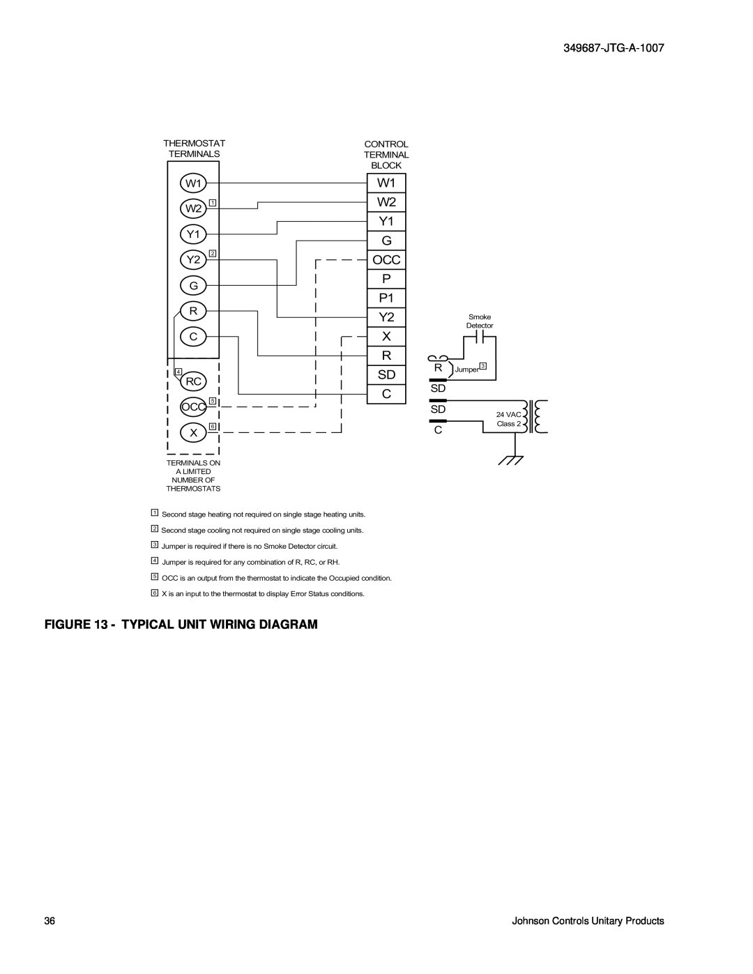
FIGURE 3 - TYPICAL J**DJ FIELD WIRING DIAGRAM
TABLE 24 ELECTRIC HEAT CORRECTION FACTORS
FIGURE 4 - FRONT VIEW DIMENSIONS
TABLE 25 UTILITIES ENTRY DATA
HOLE
USED FOR
FIGURE 5 - REAR VIEW DIMENSIONS
Dimensions listed are for side
Field Accessories for Side
duct flange openings see
TABLE 26 MINIMUM CLEARANCES
FIGURE 7 - UNIT CENTER OF GRAVITY
FIGURE 8 - TYPICAL UNIT APPLICATIONS
ROOF JACK INSTALLATION ROOF CURB INSTALLATION
SLAB ON GROUND INSTALLATION
FIGURE 9 - FOUR AND SIX POINT LOADS
TABLE 27 FOUR AND SIX POINT LOADS
Total
4 Point Loads lbs
FIGURE 10 - UNIT ROOF CURB DIMENSIONS
FIGURE 11 - ROOF CURB DUCT OPENINGS DIMENSION
FIGURE 12 - CUT AWAY OF ROOF CURB
Page
GUIDE SPECIFICATIONS
GENERAL
DESCRIPTION
OUTDOOR CONDENSER FAN ASSEMBLY
REFRIGERANT COMPONENTS
UNIT CONTROLS
GAS HEATING SECTION J**DJN MODELS
UNIT OPERATING CHARACTERISTICS
ELECTRIC HEATING J**DJC/E MODELS
ELECTRICAL REQUIREMENTS
STANDARD LIMITED WARRANTIES
OTHER PRE-ENGINEEREDACCESSORIES AVAILABLE
Top
Page
Image
Contents