ADJUSTMENT OF MANIFOLD GAS PRESSURE & INPUT RATE

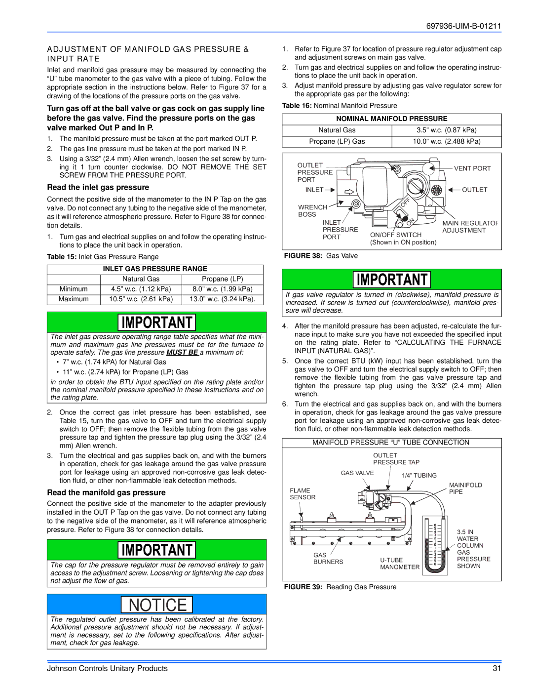
Inlet and manifold gas pressure may be measured by connecting the “U” tube manometer to the gas valve with a piece of tubing. Follow the appropriate section in the instructions below. Refer to Figure 37 for a drawing of the locations of the pressure ports on the gas valve.

Turn gas off at the ball valve or gas cock on gas supply line before the gas valve. Find the pressure ports on the gas valve marked Out P and In P.

1.

The manifold pressure must be taken at the port marked OUT P.

2.

The gas line pressure must be taken at the port marked IN P.

3.

Using a 3/32” (2.4 mm) Allen wrench, loosen the set screw by turn-

697936-UIM-B-01211

1.Refer to Figure 37 for location of pressure regulator adjustment cap and adjustment screws on main gas valve.

2.Turn gas and electrical supplies on and follow the operating instruc- tions to place the unit back in operation.

3.Adjust manifold pressure by adjusting gas valve regulator screw for the appropriate gas per the following:

Table 16: Nominal Manifold Pressure

NOMINAL MANIFOLD PRESSURE

Natural Gas

3.5" w.c. (0.87 kPa)


Propane (LP) Gas

10.0" w.c. (2.488 kPa)


ing it 1 turn counter clockwise. DO NOT REMOVE THE SET

SCREW FROM THE PRESSURE PORT.

Read the inlet gas pressure

Connect the positive side of the manometer to the IN P Tap on the gas valve. Do not connect any tubing to the negative side of the manometer, as it will reference atmospheric pressure. Refer to Figure 38 for connec- tion details.

1.Turn gas and electrical supplies on and follow the operating instruc- tions to place the unit back in operation.

OUTLET

PRESSURE

PORT

INLET

WRENCH BOSS INLET

PRESSURE PORT


VENT PORT


OUTLET

OFF


ON

MAIN REGULATOR

ON/OFF SWITCH

ADJUSTMENT


(Shown in ON position)


Table 15: Inlet Gas Pressure Range


INLET GAS PRESSURE RANGE


Natural Gas

Propane (LP)

Minimum

4.5” w.c. (1.12 kPa)

8.0” w.c. (1.99 kPa)

Maximum

10.5” w.c. (2.61 kPa)

13.0” w.c. (3.24 kPa).

The inlet gas pressure operating range table specifies what the mini- mum and maximum gas line pressures must be for the furnace to operate safely. The gas line pressure MUST BE a minimum of:

7” w.c. (1.74 kPA) for Natural Gas

11” w.c. (2.74 kPA) for Propane (LP) Gas

in order to obtain the BTU input specified on the rating plate and/or the nominal manifold pressure specified in these instructions and on the rating plate.

2.Once the correct gas inlet pressure has been established, see Table 15, turn the gas valve to OFF and turn the electrical supply switch to OFF; then remove the flexible tubing from the gas valve pressure tap and tighten the pressure tap plug using the 3/32” (2.4 mm) Allen wrench.

3.Turn the electrical and gas supplies back on, and with the burners in operation, check for gas leakage around the gas valve pressure port for leakage using an approved non-corrosive gas leak detec- tion fluid, or other non-flammable leak detection methods.

Read the manifold gas pressure

Connect the positive side of the manometer to the adapter previously installed in the OUT P Tap on the gas valve. Do not connect any tubing to the negative side of the manometer, as it will reference atmospheric pressure. Refer to Figure 38 for connection details.

The cap for the pressure regulator must be removed entirely to gain access to the adjustment screw. Loosening or tightening the cap does not adjust the flow of gas.

NOTICE

The regulated outlet pressure has been calibrated at the factory. Additional pressure adjustment should not be necessary. If adjust- ment is necessary, set to the following specifications. After adjust- ment, check for gas leakage.

FIGURE 38: Gas Valve

If gas valve regulator is turned in (clockwise), manifold pressure is increased. If screw is turned out (counterclockwise), manifold pres- sure will decrease.

4.After the manifold pressure has been adjusted, re-calculate the fur- nace input to make sure you have not exceeded the specified input on the rating plate. Refer to “CALCULATING THE FURNACE INPUT (NATURAL GAS)”.

5.Once the correct BTU (kW) input has been established, turn the gas valve to OFF and turn the electrical supply switch to OFF; then remove the flexible tubing from the gas valve pressure tap and tighten the pressure tap plug using the 3/32” (2.4 mm) Allen wrench.

6.Turn the electrical and gas supplies back on, and with the burners in operation, check for gas leakage around the gas valve pressure port for leakage using an approved non-corrosive gas leak detec- tion fluid, or other non-flammable leak detection methods.

MANIFOLD PRESSURE “U” TUBE CONNECTION


OUTLET


PRESSURE TAP


GAS VALVE

1/4” TUBING


FLAME


MAINIFOLD


PIPE

SENSOR


3.5 IN


WATER


COLUMN

GAS


GAS


U-TUBE

PRESSURE

BURNERS


MANOMETER

SHOWN


FIGURE 39: Reading Gas Pressure

Johnson Controls Unitary Products

31

Page 31
Image 31
Johnson Controls TM9X*MP installation manual Adjustment of Manifold GAS Pressure & Input Rate, Read the inlet gas pressure

TM9X*MP specifications

The Johnson Controls TM9X*MP series represents a significant advancement in the realm of HVAC control systems, positioning itself as a versatile solution for both commercial and residential applications. Renowned for its intelligent design and user-friendly interface, the TM9X*MP series aims to enhance energy efficiency and provide comfort to its users.

One of the standout features of the TM9X*MP series is its advanced communication capabilities. It employs the latest communication protocols, including BACnet and Modbus, which facilitate seamless integration with various building management systems. This connectivity ensures that users can monitor and control their HVAC systems remotely, providing unparalleled convenience and control over their environment.

Further enhancing its adaptability, the TM9X*MP series supports a wide range of HVAC equipment, including heat pumps, rooftop units, and variable air volume systems. This flexibility makes it an ideal choice for diverse applications, catering to the specific needs of different building types and operational requirements.

Energy efficiency is a significant focus of the TM9X*MP series. The system is equipped with advanced algorithms that optimize HVAC performance based on real-time data inputs. By utilizing trends in occupancy and weather forecasts, the TM9X*MP can make informed adjustments to operation schedules and settings, ensuring minimal energy wastage while maintaining optimal comfort levels.

Another notable characteristic of the TM9X*MP series is its intuitive touchscreen interface. This user-centric design makes it easy for operators to navigate through various settings and configurations, reducing the complexity often associated with HVAC controls. The interface can display vital system information, including energy consumption metrics and system diagnostics, empowering users to make informed decisions regarding their HVAC systems.

The TM9X*MP series also prioritizes robustness and reliability. Built with high-quality components, these controllers are designed to withstand varying environmental conditions, ensuring extensive operational longevity. Furthermore, the comprehensive support and resources provided by Johnson Controls augment the TM9X*MP series’ reputation for exceptional service and performance.

In conclusion, the Johnson Controls TM9X*MP series is a versatile and reliable solution for modern HVAC control needs. Its advanced communication capabilities, energy-efficient algorithms, user-friendly interface, and robust design make it a strong contender in the market, catering to the dynamic demands of contemporary heating and cooling applications. Whether for large commercial buildings or smaller residential units, the TM9X*MP series stands out as a top-tier choice for HVAC management.