697936-UIM-B-01211

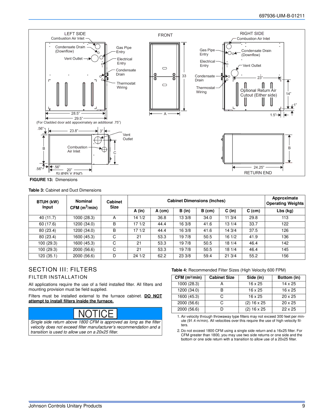
LEFT SIDE

Combustion Air Inlet

Condensate Drain

Gas Pipe

(Downflow)

Entry

Vent Outlet

Electrical


Entry


Condensate


Drain


Thermostat


Wiring

28.5”


29.5”


(For Cladded door add appoximately an additional .75”)

FRONT

A


RIGHT SIDE


Combustion Air Inlet


Gas Pipe

Condensate Drain


Entry

(Downflow)


Electrical


Entry

Vent Outlet


33

Condensate

23”


Drain


Thermostat

Optional Return Air


Wiring

14”


Cutout (Either side)


1”


1.5”


.56”

23.8”

3”


Vent


Outlet

B

Combustion

B


Air Inlet

C


.56”

.56”

24.25”

20”


SUPPLY END


RETURN END


FIGURE 13: Dimensions


Table 3: Cabinet and Duct Dimensions


BTUH (kW)

Nominal


Cabinet


Cabinet Dimensions (Inches)


Approximate


Operating Weights

Input

CFM (m3/min)


Size


A (in)

A (cm)

B (in)

B (cm)

C (in)

C (cm)

Lbs (kg)


40 (11.7)

1000 (28.3)


A

14 1/2

36.8

13 3/8

34.0

11 3/4

29.8

113

60 (17.6)

1200 (34.0)


B

17 1/2

44.4

16 3/8

41.6

13 1/4

33.7

122

80 (23.4)

1200 (34.0)


B

17 1/2

44.4

16 3/8

41.6

14 3/4

37.5

126

80 (23.4)

1600 (45.3)


C

21

53.3

19 7/8

50.5

16 1/2

41.9

136

100 (29.3)

1600 (45.3)


C

21

53.3

19 7/8

50.5

18 1/4

46.4

142

100 (29.3)

2000 (56.6)


C

21

53.3

19 7/8

50.5

18 1/4

46.4

145

120 (35.1)

2000 (56.6)


D

24 1/2

62.2

23 3/8

59.4

21 3/4

55.2

156

SECTION III: FILTERS

FILTER INSTALLATION

All applications require the use of a field installed filter. All filters and mounting provision must be field supplied.

Filters must be installed external to the furnace cabinet. DO NOT attempt to install filters inside the furnace.

NOTICE

Single side return above 1800 CFM is approved as long as the filter velocity does not exceed filter manufacturer’s recommendation and a transition is used to allow use on a 20x25 filter.

Table 4: Recommended Filter Sizes (High Velocity 600 FPM)

CFM (m³/min)

Cabinet Size

Side (in)

Bottom (in)

1000 (28.3)

A

16 x 25

14 x 25

1200 (34.0)

B

16 x 25

16 x 25

1600 (45.3)

C

16 x 25

20 x 25

2000 (56.6)

C

(2) 16 x 25

20 x 25

2000 (56.6)

D

(2) 16 x 25

22 x 25

1.Air velocity through throwaway type filters may not exceed 300 feet per min- ute (91.4 m/min). All velocities over this require the use of high velocity fil- ters.

2.Do not exceed 1800 CFM using a single side return and a 16x25 filter. For CFM greater than 1800, you may use two side returns or one side and the bottom or one side return with a transition to allow use of a 20x25 filter.

Johnson Controls Unitary Products

9

Page 9
Image 9
Johnson Controls TM9X*MP installation manual Section III Filters, Filter Installation, Btuh kW, Cabinet Dimensions Inches

TM9X*MP specifications

The Johnson Controls TM9X*MP series represents a significant advancement in the realm of HVAC control systems, positioning itself as a versatile solution for both commercial and residential applications. Renowned for its intelligent design and user-friendly interface, the TM9X*MP series aims to enhance energy efficiency and provide comfort to its users.

One of the standout features of the TM9X*MP series is its advanced communication capabilities. It employs the latest communication protocols, including BACnet and Modbus, which facilitate seamless integration with various building management systems. This connectivity ensures that users can monitor and control their HVAC systems remotely, providing unparalleled convenience and control over their environment.

Further enhancing its adaptability, the TM9X*MP series supports a wide range of HVAC equipment, including heat pumps, rooftop units, and variable air volume systems. This flexibility makes it an ideal choice for diverse applications, catering to the specific needs of different building types and operational requirements.

Energy efficiency is a significant focus of the TM9X*MP series. The system is equipped with advanced algorithms that optimize HVAC performance based on real-time data inputs. By utilizing trends in occupancy and weather forecasts, the TM9X*MP can make informed adjustments to operation schedules and settings, ensuring minimal energy wastage while maintaining optimal comfort levels.

Another notable characteristic of the TM9X*MP series is its intuitive touchscreen interface. This user-centric design makes it easy for operators to navigate through various settings and configurations, reducing the complexity often associated with HVAC controls. The interface can display vital system information, including energy consumption metrics and system diagnostics, empowering users to make informed decisions regarding their HVAC systems.

The TM9X*MP series also prioritizes robustness and reliability. Built with high-quality components, these controllers are designed to withstand varying environmental conditions, ensuring extensive operational longevity. Furthermore, the comprehensive support and resources provided by Johnson Controls augment the TM9X*MP series’ reputation for exceptional service and performance.

In conclusion, the Johnson Controls TM9X*MP series is a versatile and reliable solution for modern HVAC control needs. Its advanced communication capabilities, energy-efficient algorithms, user-friendly interface, and robust design make it a strong contender in the market, catering to the dynamic demands of contemporary heating and cooling applications. Whether for large commercial buildings or smaller residential units, the TM9X*MP series stands out as a top-tier choice for HVAC management.