Johnson Controls TM8M/TMLM*MP Section IV GAS Piping, GAS Safety, GAS Piping Installation

Models: LM8M/LMLM*MP TM8M/TMLM*MP CM8M/CMLM*MP YM8M/YMLM*MP

1 28
Download 28 pages 19.77 Kb
Page 9
Image 9

368261-UIM-A-0508

HORIZONTAL APPLICATION

Horizontal Filters

All filters and mounting provision must be field supplied. All installa- tions must have a filter installed.

Any branch duct (rectangular or round duct) attached to the plenum must attach to the vertical plenum before the filter. The use of straps and / or supports is required to support the weight of the external filter box.

Downflow Filters

Downflow furnaces typically are installed with the filters located above the furnace, extending into the return air plenum or duct. Any branch duct (rectangular or round duct) attached to the plenum must attach to the vertical plenum above the filter height.

Filter(s) may be located in the duct system external to the furnace using an external duct filter box attached to the furnace plenum or at the end of the duct in a return filter grille(s). The use of straps and/or supports is required to support the weight of the external filter box.

SECTION IV: GAS PIPING

GAS SAFETY

An overpressure protection device, such as a pressure regulator, must be installed in the gas piping system upstream of the furnace and must act to limit the downstream pressure to the gas valve so it does not exceed 0.5 PSI (14" w.c. (3.48 kPa). Pressures exceeding

0.5PSI (14” w.c. (3.48 kPa) at the gas valve will cause damage to the gas valve, resulting in a fire or explosion or cause damage to the furnace or some of its components that will result in property damage and loss of life.

On/Off

Main

Regulator

Knob

Adjustment


Inlet


Outlet


Pressure


Pressure

Tap


Tap


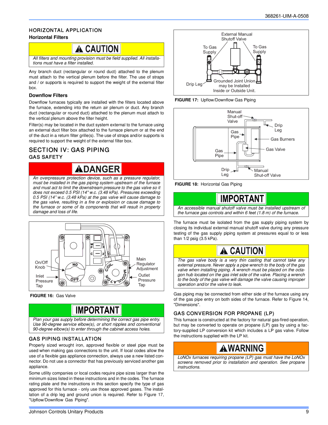
FIGURE 16: Gas Valve


Plan your gas supply before determining the correct gas pipe entry. Use 90-degree service elbow(s), or short nipples and conventional 90-degree elbow(s) to enter through the cabinet access holes.

GAS PIPING INSTALLATION

Properly sized wrought iron, approved flexible or steel pipe must be used when making gas connections to the unit. If local codes allow the use of a flexible gas appliance connection, always use a new listed con- nector. Do not use a connector that has previously serviced another gas appliance.

Some utility companies or local codes require pipe sizes larger than the minimum sizes listed in these instructions and in the codes. The furnace rating plate and the instructions in this section specify the type of gas approved for this furnace - only use those approved gases. The instal- lation of a drip leg and ground union is required. Refer to Figure 17, "Upflow/Downflow Gas Piping".


External Manual


Shutoff Valve

To Gas


To Gas

Supply


Supply


Drip Leg

Grounded Joint Union


may be Installed


Inside or Outside Unit.


FIGURE 17: Upflow/Downflow Gas Piping


Manual


Shut-off


Valve

Drip


Gas

Leg


Pipe

Gas Burners


Gas

Gas Valve


Pipe


Drip

Manual


Leg

Shut-off Valve


FIGURE 18: Horizontal Gas Piping


An accessible manual shutoff valve must be installed upstream of the furnace gas controls and within 6 feet (1.8 m) of the furnace.

The furnace must be isolated from the gas supply piping system by closing its individual external manual shutoff valve during any pressure testing of the gas supply piping system at pressures equal to or less than 1/2 psig (3.5 kPa).

The gas valve body is a very thin casting that cannot take any external pressure. Never apply a pipe wrench to the body of the gas valve when installing piping. A wrench must be placed on the octa- gon hub located on the gas inlet side of the valve. Placing a wrench to the body of the gas valve will damage the valve causing improper operation and/or the valve to leak.

Gas piping may be connected from either side of the furnace using any of the gas pipe entry on both sides of the furnace. Refer to Figure 14, "Dimensions".

GAS CONVERSION FOR PROPANE (LP)

This furnace is constructed at the factory for natural gas-fired operation, but may be converted to operate on propane (LP) gas by using a fac- tory-supplied LP conversion kit which includes a LP gas valve. Follow the instructions supplied with the LP kit.

LoNOx furnaces requiring propane (LP) gas must have the LoNOx screens removed prior to installation and operation. See propane instructions.

Johnson Controls Unitary Products

9

Page 9
Image 9
Johnson Controls TM8M/TMLM*MP Section IV GAS Piping, GAS Safety, GAS Piping Installation, GAS Conversion for Propane LP

LM8M/LMLM*MP, TM8M/TMLM*MP, CM8M/CMLM*MP, YM8M/YMLM*MP specifications

Johnson Controls TM8M/TMLM*MP, YM8M/YMLM*MP, LM8M/LMLM*MP, and CM8M/CMLM*MP are advanced temperature controllers designed for a wide range of applications in heating, ventilation, and air conditioning (HVAC) systems. These models stand out due to their robust features, cutting-edge technologies, and specific characteristics that cater to both residential and commercial environments.

One of the main features of the TM8M/TMLM*MP series is its user-friendly interface that incorporates a large, easy-to-read display. This allows for quick adjustments and monitoring of temperature settings, making it accessible for both skilled technicians and everyday users. The intuitive design ensures that users can efficiently navigate through various settings and configurations.

Another notable characteristic is the flexibility of these controllers. The series supports multiple sensor configurations, enabling the integration of both wired and wireless sensors. This adaptability allows users to customize their climate control systems according to specific needs and room layouts, ultimately enhancing comfort and energy efficiency.

The TM8M/TMLM*MP and its counterparts are equipped with sophisticated algorithms that optimize energy consumption. By utilizing predictive maintenance and intelligent analytics, these controllers can adjust settings dynamically based on real-time data. This not only helps in reducing operational costs but also prolongs the lifespan of HVAC equipment.

Incorporating advanced communication protocols is a hallmark of the Johnson Controls series. The TM8M and CM8M models support modern systems such as BACnet and Modbus, allowing seamless integration with building management systems (BMS). This compatibility ensures that users can maintain centralized control over multiple systems, enhancing overall operational efficiency.

Additionally, the series is robustly constructed to withstand harsh environmental conditions. Its durable casing and reliable components ensure long-term performance, making it suitable for a variety of settings, including industrial facilities and commercial properties.

Safety features are also integral to the design of the TM8M/TMLM*MP and related models. Built-in safeguards protect against over-temperature and other potential hazards, ensuring reliability and peace of mind for operators.

In summary, Johnson Controls TM8M/TMLM*MP, YM8M/YMLM*MP, LM8M/LMLM*MP, and CM8M/CMLM*MP controllers represent a convergence of user-friendly design, advanced technology, flexibility, and safety. Their ability to adapt to diverse applications while optimizing energy use makes them a critical component in modern HVAC systems, ensuring comfort and efficiency in every environment.