368261-UIM-A-0508

An unconfined space is not less than 50 cu.ft (1.42 m3) per 1,000 Btu/ hr (0.2928 kW) input rating for all of the appliances installed in that area.

Rooms communicating directly with the space containing the appli- ances are considered part of the unconfined space, if openings are fur- nished with openings or louvers.

A confined space is an area with less than 50 cu.ft (1.42 m3) per 1,000 Btu/hr (0.2928 kW) input rating for all of the appliances installed in that area. The following must be considered to obtain proper air for combus- tion and ventilation in confined spaces.

Combustion Air Source From Outdoors

The blocking effects of louvers, grilles and screens must be given con- sideration in calculating free area. If the free area of a specific louver or grille is not known, refer to Table 7, to estimate free area.

Table 7: Estimated Free Area

Wood or Metal

Wood 20-25%*

Louvers or Grilles

Metal 60-70% *


Screens+

1/4” (0.635 cm)

mesh or larger 100%


* Do not use less than 1/4”(0.635 cm) mesh

+Free area of louvers and grille varies widely; the installer should follow louver or grille manufacturer’s instructions.

Dampers, Louvers and Grilles (Canada Only)

1.The free area of a supply air opening shall be calculated by sub- tracting the blockage area of all fixed louvers grilles or screens from the gross area of the opening.

2.Apertures in a fixed louver, a grille, or screen shall have no dimen- sion smaller than 0.25” (0.64 cm).

3.A manually operated damper or manually adjustable louvers are not permitted for use.

4.A automatically operated damper or automatically adjustable lou- vers shall be interlocked so that the main burner cannot operate unless either the damper or the louver is in the fully open position.

When a Category I furnace is removed or replaced, the original venting system may no longer be correctly sized to properly vent the attached appliances.

An improperly sized vent system can cause CARBON MONOXIDE to spill into the living space causing personal injury, and or death.

Table 8: Unconfined Space Minimum Area in Square Inch

BTUH Input Rating


Minimum Free Area in Square Feet


Required for Each Opening


60,000


60 (387 cm2)


80,000


80 (516 cm2)


100,000


100 (645 cm2)


120,000


120 (742 cm2)


Table 9: Free Area


BTUH Input


Minimum Free Area Required for Each Opening


Horizontal Duct


Vertical Duct or

Round Duct


Rating


Opening to Outside


(2,000 BTUH)


(4,000 BTUH)


(4,000 BTUH)


60,000


30 in2 (193 cm2)


15 in2 (97 cm2)

5” (13 cm)


80,000


40 in2 (258 cm2)


20 in2 (129 cm2)

5” (13 cm)


100,000


50 in2 (322 cm2)


25 in2 (161 cm2)

6” (15 cm)


120,000


60 in2 (387 cm2)


30 in2 (193 cm2)

7” (18 cm)


EXAMPLE:

Determining Free Area.


Appliance


1 Appliance


2 Total Input


100,000

+


30,000 = (130,000 4,000) = 32.5 Sq. In. Vertical


Appliance


1 Appliance


2 Total Input


100,000

+


30,000 = (130,000 2,000) = 65 Sq. In. Horizontal


Gable

Vent


Ventilated

Optional

Attic

Top Above

Inlet (a)

Insulation


Soffit

Outlet

Vent

Air (a)


Gas


Water


Heater


Ventilated


Crawl Space

Gas

VentGable

Vent

Ventilated

Attic

Top Above

Insulation

Soffit

Vent

Furnace

Gas


Water

Inlet

Heater

Air (b)


Gas Vent

Furnace

Gas

Vent

Outlet

Air (b)

Inlet

Inlet

Heater

Furnace


Gas


Water


Air (a)

Air (b)


Outlet Air (a)

Inlet

Air (a)

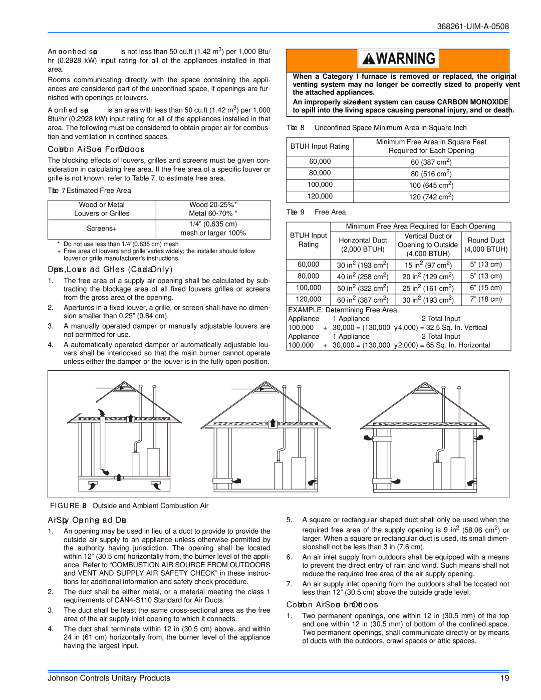
FIGURE 28: Outside and Ambient Combustion Air

Air Supply Openings and Ducts

1.An opening may be used in lieu of a duct to provide to provide the outside air supply to an appliance unless otherwise permitted by the authority having jurisdiction. The opening shall be located within 12” (30.5 cm) horizontally from, the burner level of the appli- ance. Refer to “COMBUSTION AIR SOURCE FROM OUTDOORS and VENT AND SUPPLY AIR SAFETY CHECK” in these instruc- tions for additional information and safety check procedure.

2.The duct shall be either metal, or a material meeting the class 1 requirements of CAN4-S110 Standard for Air Ducts.

3.The duct shall be least the same cross-sectional area as the free area of the air supply inlet opening to which it connects.

4.The duct shall terminate within 12 in (30.5 cm) above, and within 24 in (61 cm) horizontally from, the burner level of the appliance having the largest input.

5.A square or rectangular shaped duct shall only be used when the required free area of the supply opening is 9 in2 (58.06 cm2) or larger. When a square or rectangular duct is used, its small dimen- sionshall not be less than 3 in (7.6 cm).

6.An air inlet supply from outdoors shall be equipped with a means to prevent the direct entry of rain and wind. Such means shall not reduce the required free area of the air supply opening.

7.An air supply inlet opening from the outdoors shall be located not less than 12” (30.5 cm) above the outside grade level.

Combustion Air Source from Outdoors

1.Two permanent openings, one within 12 in (30.5 mm) of the top and one within 12 in (30.5 mm) of bottom of the confined space, Two permanent openings, shall communicate directly or by means of ducts with the outdoors, crawl spaces or attic spaces.

Johnson Controls Unitary Products

19

Page 19
Image 19
Johnson Controls CM8M/CMLM*MP Combustion Air Source From Outdoors, Dampers, Louvers and Grilles Canada Only, Free Area

LM8M/LMLM*MP, TM8M/TMLM*MP, CM8M/CMLM*MP, YM8M/YMLM*MP specifications

Johnson Controls TM8M/TMLM*MP, YM8M/YMLM*MP, LM8M/LMLM*MP, and CM8M/CMLM*MP are advanced temperature controllers designed for a wide range of applications in heating, ventilation, and air conditioning (HVAC) systems. These models stand out due to their robust features, cutting-edge technologies, and specific characteristics that cater to both residential and commercial environments.

One of the main features of the TM8M/TMLM*MP series is its user-friendly interface that incorporates a large, easy-to-read display. This allows for quick adjustments and monitoring of temperature settings, making it accessible for both skilled technicians and everyday users. The intuitive design ensures that users can efficiently navigate through various settings and configurations.

Another notable characteristic is the flexibility of these controllers. The series supports multiple sensor configurations, enabling the integration of both wired and wireless sensors. This adaptability allows users to customize their climate control systems according to specific needs and room layouts, ultimately enhancing comfort and energy efficiency.

The TM8M/TMLM*MP and its counterparts are equipped with sophisticated algorithms that optimize energy consumption. By utilizing predictive maintenance and intelligent analytics, these controllers can adjust settings dynamically based on real-time data. This not only helps in reducing operational costs but also prolongs the lifespan of HVAC equipment.

Incorporating advanced communication protocols is a hallmark of the Johnson Controls series. The TM8M and CM8M models support modern systems such as BACnet and Modbus, allowing seamless integration with building management systems (BMS). This compatibility ensures that users can maintain centralized control over multiple systems, enhancing overall operational efficiency.

Additionally, the series is robustly constructed to withstand harsh environmental conditions. Its durable casing and reliable components ensure long-term performance, making it suitable for a variety of settings, including industrial facilities and commercial properties.

Safety features are also integral to the design of the TM8M/TMLM*MP and related models. Built-in safeguards protect against over-temperature and other potential hazards, ensuring reliability and peace of mind for operators.

In summary, Johnson Controls TM8M/TMLM*MP, YM8M/YMLM*MP, LM8M/LMLM*MP, and CM8M/CMLM*MP controllers represent a convergence of user-friendly design, advanced technology, flexibility, and safety. Their ability to adapt to diverse applications while optimizing energy use makes them a critical component in modern HVAC systems, ensuring comfort and efficiency in every environment.