Contents
Colour Television
15 cm
Confirm your TV’s functions
Knowing your TV’s features
Main features
Remote control buttons and basic functions
Press
Remote control buttons and basic functions
How to operate menus and menus locations
TV buttons and functions
Front of the TV
AV-21V315
Rear of the TV
Setting up your TV
Turn off the equipment including the TV before connecting
Setting up your TV
Making the initial settings
Colour System
Basic setting for picture
Picture Mode
Basic setting for picture
Picture Setting
Select the Picture Setting in Picture menu, then adjust
White Balance
Advanced setting for picture
AI ECO Sensor ECO
Compress
Blue Back
Basic setting for sound
Sound Mode
Sound System
Balance
Advanced setting for sound
AI Volume
Cinema Surround
Super Bass Bass
Auto Signal Detect
DVD Picture Mode
DVD function
Tint Colour
Customized setting
OFF Timer
VNR
Language
Customized setting
VIDEO-2 Setting
Setup Tour
Select Setup Tour in the Install menu
Auto Program
TV channel presetting
To register the TV channels automatically
To add in the new channel Insert in the Edit menu
TV channel presetting CH/CC number
Channel No Country
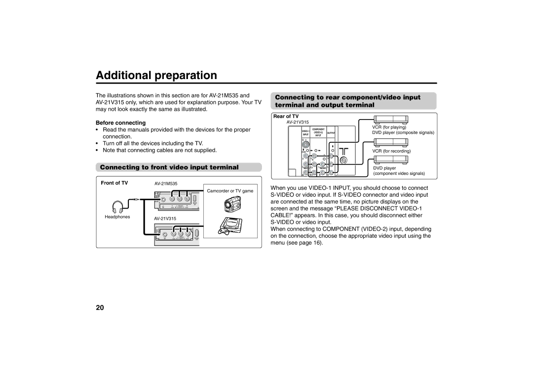
Additional preparation
Connecting to front video input terminal
Before connecting
When you mount the unit, make sure that the mounting pin
AV-21M535 only
Top of the TV
Off the top of the TV. This may cause damage or cause
Troubleshooting
Specifications
Weight 24 kg
Model AV-21M315 AV-21V315 AV-25M315
TV RF system Colour system
Model AV-21M515 AV-25M515 AV-21M535
TV RF system I, D, K, M Colour system
PAL, SECAM, Ntsc 3.58 MHz, Ntsc 4.43 MHz
Picture tube 649 mm
AV-21M335 AV-21M315 AV-21V315 AV-25M335 AV-25M315 AV-25V315
15 cm
Favorite CH Channel
Remote control buttons and basic functions
VNR
AV-25V315
AV-21M335
VHF/UHF outdoor aerial AV-25V315
Vieät
Auto PAL Secam NTSC3.58
Picture Booster
Advanced setting for picture
Basic setting for sound
For attaching the Twin Port Bass Blaster unit, please see
DVD function
Customized setting
VIDEO-2 Setting
TV channel presetting
To add in the new channel Insert in the Edit menu
TV channel presetting CH/CC number
Headphones AV-25V315
AV-21M335, AV25M335 only
See
Power input
+ 7 W Rated power output Speaker
Weight
Audio output
Victor Company of Japan, Limited FLE-JMT