BD-X201M specifications
The JVC BD-X201M is a high-performance professional Blu-ray Disc player that showcases a blend of advanced technologies and features, making it a valuable asset for broadcasting, production, and home entertainment applications. This model stands out for its ability to handle a wide array of formats while providing exceptional playback quality.One of the standout features of the BD-X201M is its support for Ultra HD Blu-ray, allowing for playback of 4K content at resolutions up to 3840 x 2160. This capability ensures that users can enjoy stunning visuals with four times the detail of standard Full HD. The player also supports HDR (High Dynamic Range) and 10-bit color depth, which significantly enhances the color accuracy and contrast, creating more lifelike images.
The BD-X201M integrates JVC's proprietary image processing technology, which optimizes video quality by reducing noise and enhancing clarity. Additionally, the player features advanced scaling capabilities, allowing for upscaling of lower-resolution content to near 4K quality. This ensures that users can enjoy a broad range of content with the highest possible fidelity.
In terms of audio, the JVC BD-X201M supports various surround sound formats, including Dolby Atmos and DTS:X, providing an immersive audio experience that complements its stunning video output. The player is equipped with balanced and unbalanced audio outputs, allowing flexibility in how the audio connects to professional sound systems.
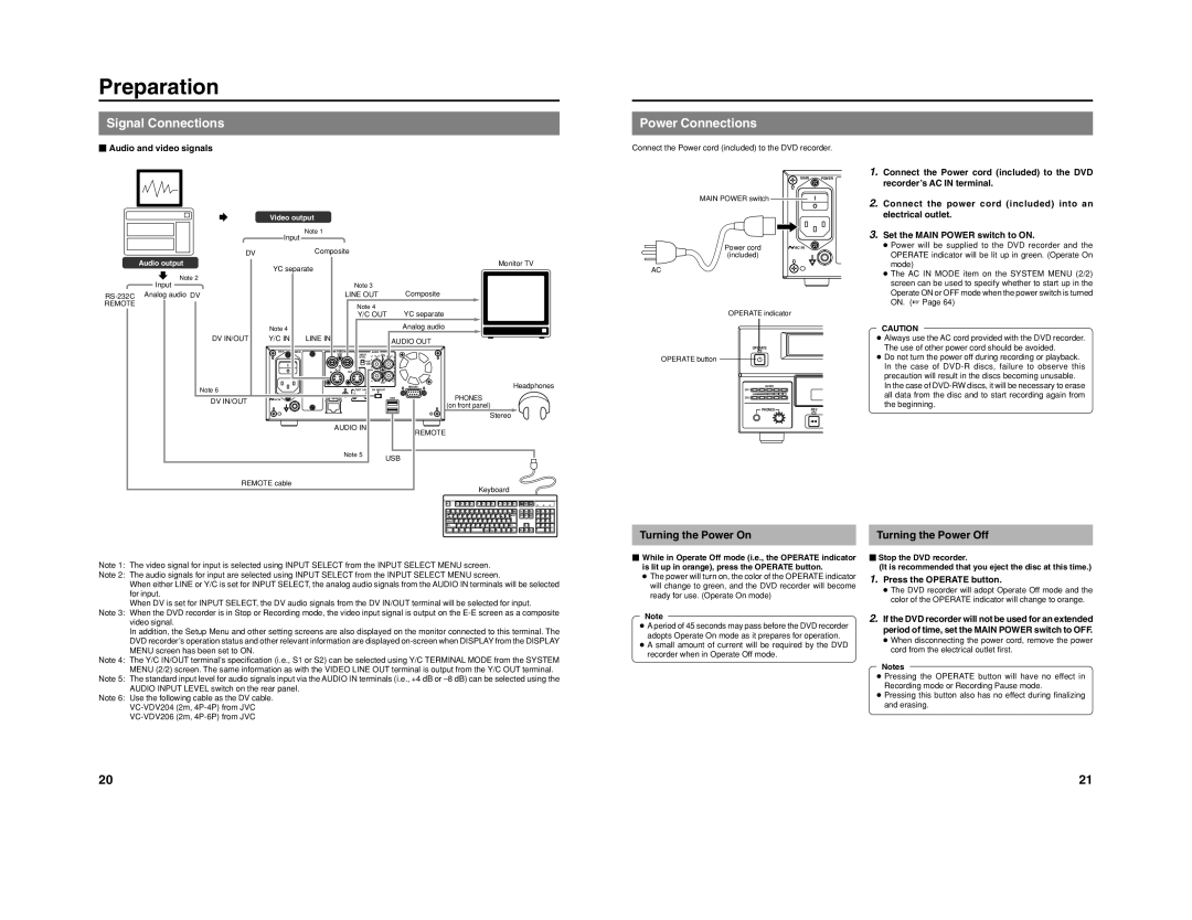
Connectivity is another area where the BD-X201M excels. It comes with HDMI outputs, USB ports, and a host of other interfaces suitable for integration into professional setups. It also includes IP streaming capabilities, enabling users to stream content over a network, thus providing convenience in content management and distribution.
The user interface of the BD-X201M is designed for intuitive navigation, making it easy for users to access their media libraries. It also incorporates customizable settings to cater to different environments, whether for a professional theater or home use.
In summary, the JVC BD-X201M is a feature-rich Blu-ray player that combines advanced imaging and audio technologies with versatile connectivity options. Its ability to handle 4K HDR content, coupled with professional audio formats, makes it an ideal choice for both home cinema enthusiasts and professionals in the entertainment industry. Its robust build quality and performance capabilities ensure that it meets the demands of any high-quality viewing experience.

