8
2 CONTROLS, CONNECTORS AND DISPLAYS

2-1 Front panel

PHONES MIC
REMOTE
LOCAL
EJECT
OPERATE
REC LEVEL
CH-2/4
CH-1/3
SHIFT
SET
SELECT
SHIFT
MENU
HOLD
V.IN/A.MONI A.OUT COUNTER
SHIFT A. DUB
ADVANCE PRESET
DV CTL
TC
UB
CH-1/2
CH-3/4
Y/C
(CPN)
LINE
L
R
MIX
MIX
REW STOP FF
REC PLAY
PAUSE
ON/OFF
MENU
OVER
OVER
HMSF
AUDLOCK
SP
32k 48k
SLAVE PB NDF
SERVORF
DEW
AUTO OFF
HOLD
CH 2/4
CH 1/3
VIDEO CASSETTE RECORDER BR-DV600UA
dB4030 20 10 0
1
2
3
4
5
6
7
8
9
0
!
@
#$%
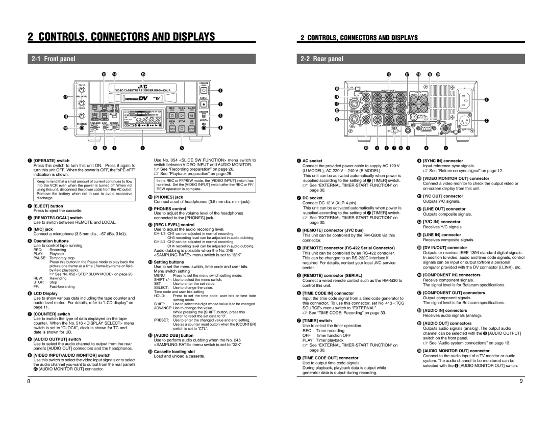
1[OPERATE] switch
Press this switch to turn this unit ON. Press it again to
turn this unit OFF. When the power is OFF, the oPE-oFF
indication is shown.
Keep in mind that a small amount of current continues to flow
into the VCR even when the power is turned off. When not
using this unit, disconnect the power cable from the AC outlet.
Remove the battery when not in use to avoid excessive
discharge.
2[EJECT] button
Press to eject the cassette.
3[REMOTE/LOCAL] switch
Use to switch between REMOTE and LOCAL.
4[MIC] jack
Connect a microphone (3.5 mm dia., 67 dBs, 3 k).
5Operation buttons
Use to control tape running.
REC: Recording
PLAY: Playback
PAUSE: Temporary stop
Press this button in the Pause mode to play back the
picture one frame at a time ( frame-by-frame or field-
by-field playback).
See No. 052 <STEP SLOW MODE> on page 20.
REW: Rewinding
STOP: Stop
FF: Fast-forwarding
6LCD Display
Use to show various data including the tape counter and
audio level meter. For details, refer to LCD display on
page 11.
7[COUNTER] switch
Use to switch the type of data displayed on the tape
counter. When the No. 516 <DISPLAY SELECT> menu
switch is set to CLOCK, clock is shown for TC and
date is shown for UB.
8[AUDIO OUTPUT] switch
Use to select the audio channel to output from the rear
panels [AUDIO OUT] connectors and the headphones.
9[VIDEO INPUT/AUDIO MONITOR] switch
Use this switch to select the video input signals or to select
the audio channel you want to output from the rear panels
) [AUDIO MONITOR OUT] connector.
Use No. 054 <SLIDE SW FUNCTION> menu switch to
switch between VIDEO INPUT and AUDIO MONITOR.
See Recording preparation on page 26.
See Playback preparation on page 28.
In the REC or FF/REW mode, the [VIDEO INPUT] switch has
no effect. Set the [VIDEO INPUT] switch after the REC or FF/
REW operation is complete.
0[PHONES] jack
Connect a set of headphones (3.5 mm dia. mini-jack).
!PHONES control
Use to adjust the volume level of the headphones
connected to the [PHONES] jack.
@[REC LEVEL] control
Use to adjust the audio recording level.
CH-1/3: CH1 can be adjusted in normal recording.
CH3 recording level can be adjusted in audio dubbing.
CH-2/4: CH2 can be adjusted in normal recording.
CH4 recording level can be adjusted in audio dubbing.
Audio dubbing is possible when the No. 245
<SAMPLING RATE> menu switch is set to 32K.
#Setting buttons
Use to set the menu switch, time code and user bits.
Menu switch setting
MENU: Press to set the menu switch setting mode.
SHIFT +/:Use to select the menu switch.
SET: Use to enter the set value.
SELECT: Use to change the value.
Time code and user bits setting
HOLD: Press to set the time code, user bits or time date
setting mode.
SHIFT: Use to select the digit whose value is to be changed.
ADVANCE:Use to change the value.
While pressing the [SHIFT] button, press this
button to reset the set data to 0.
PRESET: Use to enter the changed value and end setting.
Use as a counter reset button when the [COUNTER]
switch is set to CTL.
$[AUDIO DUB] button
Use to perform audio dubbing when the No. 245
<SAMPLING RATE> menu switch is set to 32K.
%Cassette loading slot
Load and unload a cassette.
9

2-2 Rear panel

2 CONTROLS, CONNECTORS AND DISPLAYS
DC 12V
PGZ01945
TIMER
TIME CODE
COMPONENT
VIDEO
SYNC IN
REC
OFF
PLAY
DV
IN/OUT
REMOTE
AUDIO
2
1
SERIAL
CH 1/3
OUT
OUT
IN
IN
IN
B-Y
IN
Y/C
LINE
OUT
OUT
OUT
MONITOR
CH 2/4
MONITOR
OUT
R-Y
Y
1
2
7
8 6 0
!
95 4 3
#
@
$
%
^& ()
*
9[SYNC IN] connector
Input reference sync signals.
See Reference sync signal on page 12.
0[VIDEO MONITOR OUT] connector
Connect a video monitor to check the output video or
on-screen display from this unit.
![Y/C OUT] connector
Outputs Y/C signals.
@[LINE OUT] connector
Outputs composite signals.
#[Y/C IN] connector
Receives Y/C signals.
$[LINE IN] connector
Receives composite signals.
%[DV IN/OUT] connector
Outputs or receives IEEE 1394 standard digital signals.
In addition to video, audio and time code signals, control
signals can be input or output to/from a personal
computer provided with the DV connector (i.LINK), etc.
^[COMPONENT IN] connectors
Receive component signals.
The signal level is for Betacam specifications.
&[COMPONENT OUT] connectors
Output component signals.
The signal level is for Betacam specifications.
*[AUDIO IN] connectors
Receives audio signals (analog).
([AUDIO OUT] connectors
Outputs audio signals (analog). The output audio
channel can be selected with the 8 [AUDIO OUTPUT]
switch on the front panel.
See Audio system connections on page 13.
)[AUDIO MONITOR OUT] connector
Connect to the audio input of a TV monitor or audio
system. The audio channel to be monitored can be
selected with the 9 [AUDIO MONITOR OUT] switch.
1AC socket
Connect the provided power cable to supply AC 120 V
(U MODEL), AC 220 V 240 V (E MODEL).
This unit can be activated automatically when power is
supplied according to the setting of 7 [TIMER] switch.
See EXTERNAL TIMER-START FUNCTION on
page 30.
2DC socket
Connect DC 12 V (XLR 4-pin).
This unit can be activated automatically when power is
supplied according to the setting of 7 [TIMER] switch.
See EXTERNAL TIMER-START FUNCTION on
page 30.
3[REMOTE] connector (JVC bus)
This unit can be controlled by the RM-G800 via this
connector.
4[REMOTE] connector (RS-422 Serial Connector)
This unit can be controlled by an RS-422 controller.
This can be changed to an RS-232C interface if
required. For details, contact your local JVC service
center.
5[REMOTE] connector (SERIAL)
Connect a wired remote control such as the RM-G30 to
control this unit.
6[TIME CODE IN] connector
Input the time code signal from a time code generator to
this connector. To use this connector, set No. 413 <TCG
SOURCE> menu switch to EXTERNAL.
See TIME CODE: Recording on page 33.
7[TIMER] switch
Use to select the timer operation.
REC : Timer recording
OFF : Timer function OFF
PLAY: Timer playback
See EXTERNAL TIMER-START FUNCTION on
page 30.
8[TIME CODE OUT] connector
Use to output time code signals.
During playback, playback data is output while
generator data is output during recording.