ELECTRICAL CONNECTIONS

To prevent short circuits from occurring, while making connections, keep the battery’s negative terminal disconnected.

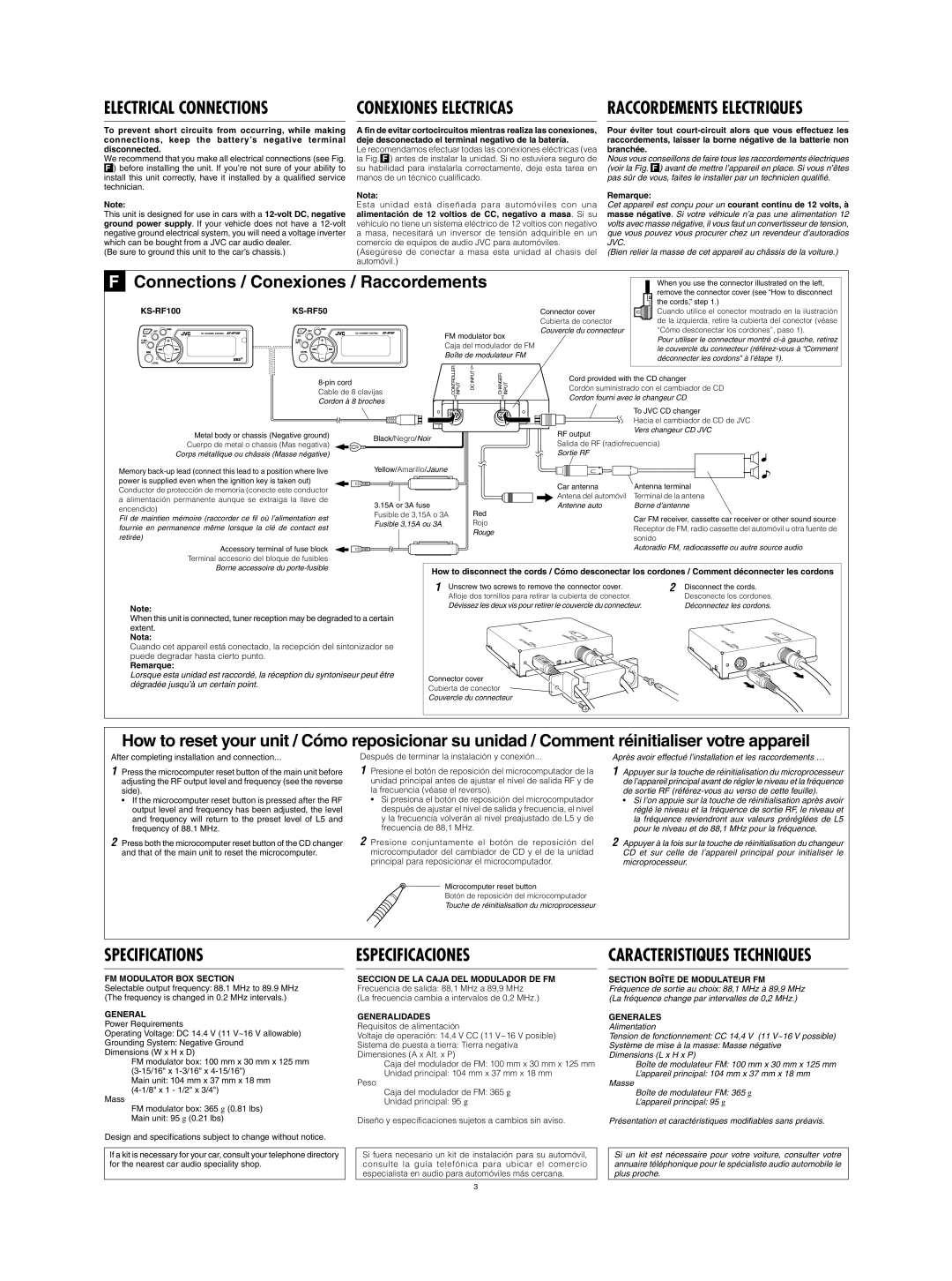
We recommend that you make all electrical connections (see Fig. ) before installing the unit. If you’re not sure of your ability to install this unit correctly, have it installed by a qualified service

technician.

CONEXIONES ELECTRICAS

A fin de evitar cortocircuitos mientras realiza las conexiones, deje desconectado el terminal negativo de la batería.

Le recomendamos efectuar todas las conexiones eléctricas (vea la Fig.) antes de instalar la unidad. Si no estuviera seguro de su habilidad para instalarla correctamente, deje esta tarea en manos de un técnico cualificado.

RACCORDEMENTS ELECTRIQUES

Pour éviter tout court-circuit alors que vous effectuez les raccordements, laisser la borne négative de la batterie non branchée.

Nous vous conseillons de faire tous les raccordements électriques (voir la Fig. ) avant de mettre l’appareil en place. Si vous n’êtes pas sûr de vous, faites le installer par un technicien qualifié.

Note:

This unit is designed for use in cars with a 12-volt DC, negative ground power supply. If your vehicle does not have a 12-volt negative ground electrical system, you will need a voltage inverter which can be bought from a JVC car audio dealer.

(Be sure to ground this unit to the car’s chassis.)

Nota:

Esta unidad está diseñada para automóviles con una alimentación de 12 voltios de CC, negativo a masa. Si su vehículo no tiene un sistema eléctrico de 12 voltios con negativo

amasa, necesitará un inversor de tensión adquirible en un comercio de equipos de audio JVC para automóviles. (Asegúrese de conectar a masa esta unidad al chasis del automóvil.)

Remarque:

Cet appareil est conçu pour un courant continu de 12 volts, à masse négative. Si votre véhicule n’a pas une alimentation 12 volts avec masse négative, il vous faut un convertisseur de tension, que vous pouvez vous procurer chez un revendeur d’autoradios JVC.

(Bien relier la masse de cet appareil au châssis de la voiture.)

F

Connections / Conexiones / Raccordements


When you use the connector illustrated on the left,


remove the connector cover (see “How to disconnect


KS-RF100

KS-RF50


the cords,” step 1.)


Connector cover

Cuando utilice el conector mostrado en la ilustración


Cubierta de conector

de la izquierda, retire la cubierta del conector (véase


FM modulator box

Couvercle du connecteur

“Cómo desconectar los cordones”, paso 1).


Pour utiliser le connecteur montré ci-à gauche, retirez


Caja del modulador de FM


le couvercle du connecteur (référez-vous à “Comment


Boîte de modulateur FM


déconnecter les cordons” à l’étape 1).


CONTROLLER INPUT

DCINPUT

CHANGER INPUT


Cable de 8 clavijas


Cordón suministrado con el cambiador de CD


8-pin cord


Cord provided with the CD changer


Cordon à 8 broches


Cordon fourni avec le changeur CD


To JVC CD changer


Hacia el cambiador de CD de JVC


Metal body or chassis (Negative ground)

Black/Negro/Noir


RF output

Vers changeur CD JVC


Cuerpo de metal o chassis (Mas negativa)


Salida de RF (radiofrecuencia)


Corps métallique ou châssis (Masse négative)


Sortie RF


Memory back-up lead (connect this lead to a position where live

Yellow/Amarillo/Jaune


power is supplied even when the ignition key is taken out)


Car antenna

Antenna terminal

Conductor de protección de memoria (conecte este conductor


Antena del automóvil

Terminal de la antena

a alimentación permanente aunque se extraiga la llave de


3.15A or 3A fuse


Antenne auto

Borne d’antenne

encendido)


Red


Fusible de 3,15A o 3A


Fil de maintien mémoire (raccorder ce fil où l’alimentation est


Car FM receiver, cassette car receiver or other sound source

Fusible 3,15A ou 3A


Rojo


fournie en permanence même lorsque la clé de contact est


Receptor de FM, radio cassette del automóvil u otra fuente de


Rouge


retirée)


sonido


Accessory terminal of fuse block


Autoradio FM, radiocassette ou autre source audio


Terminal accesorio del bloque de fusibles


Borne accessoire du porte-fusible


How to disconnect the cords / Cómo desconectar los cordones / Comment déconnecter les cordons


1

Unscrew two screws to remove the connector cover.

2

Disconnect the cords.


Afloje dos tornillos para retirar la cubierta de conector.


Desconecte los cordones.


Note:


Dévissez les deux vis pour retirer le couvercle du connecteur.

Déconnectez les cordons.


When this unit is connected, tuner reception may be degraded to a certain


extent.


Nota:


Cuando cet appareil está conectado, la recepción del sintonizador se


puede degradar hasta cierto punto.


Remarque:


Lorsque esta unidad est raccordé, la réception du syntoniseur peut être

Connector cover


dégradée jusqu’à un certain point.


Cubierta de conector


Couvercle du connecteur


How to reset your unit / Cómo reposicionar su unidad / Comment réinitialiser votre appareil

After completing installation and connection...

1Press the microcomputer reset button of the main unit before adjusting the RF output level and frequency (see the reverse side).

If the microcomputer reset button is pressed after the RF output level and frequency has been adjusted, the level and frequency will return to the preset level of L5 and frequency of 88.1 MHz.

2Press both the microcomputer reset button of the CD changer and that of the main unit to reset the microcomputer.

Después de terminar la instalación y conexión...

1Presione el botón de reposición del microcomputador de la unidad principal antes de ajustar el nivel de salida RF y de la frecuencia (véase el reverso).

Si presiona el botón de reposición del microcomputador después de ajustar el nivel de salida y frecuencia, el nivel y la frecuencia volverán al nivel preajustado de L5 y de frecuencia de 88,1 MHz.

2Presione conjuntamente el botón de reposición del microcomputador del cambiador de CD y el de la unidad principal para reposicionar el microcomputador.

Après avoir effectué l’installation et les raccordements …

1Appuyer sur la touche de réinitialisation du microprocesseur de l’appareil principal avant de régler le niveau et la fréquence de sortie RF (référez-vous au verso de cette feuille).

Si l’on appuie sur la touche de réinitialisation après avoir réglé le niveau et la fréquence de sortie RF, le niveau et la fréquence reviendront aux valeurs préréglées de L5 pour le niveau et de 88,1 MHz pour la fréquence.

2Appuyer à la fois sur la touche de réinitialisation du changeur CD et sur celle de l’appareil principal pour initialiser le microprocesseur.

Microcomputer reset button

Botón de reposición del microcomputador

Touche de réinitialisation du microprocesseur

SPECIFICATIONS

ESPECIFICACIONES

CARACTERISTIQUES TECHNIQUES

FM MODULATOR BOX SECTION

Selectable output frequency: 88.1 MHz to 89.9 MHz (The frequency is changed in 0.2 MHz intervals.)

GENERAL

Power Requirements

Operating Voltage: DC 14.4 V (11 V~16 V allowable)

Grounding System: Negative Ground Dimensions (W x H x D)

FM modulator box: 100 mm x 30 mm x 125 mm (3-15/16" x 1-3/16" x 4-15/16")

Main unit: 104 mm x 37 mm x 18 mm (4-1/8" x 1 - 1/2" x 3/4")

Mass

FM modulator box: 365 g (0.81 lbs)

Main unit: 95 g (0.21 lbs)

Design and specifications subject to change without notice.

If a kit is necessary for your car, consult your telephone directory for the nearest car audio speciality shop.

SECCION DE LA CAJA DEL MODULADOR DE FM Frecuencia de salida: 88,1 MHz a 89,9 MHz

(La frecuencia cambia a intervalos de 0,2 MHz.)

GENERALIDADES Requisitos de alimentación

Voltaje de operación: 14,4 V CC (11 V~16 V posible)

Sistema de puesta a tierra: Tierra negativa Dimensiones (A x Alt. x P)

Caja del modulador de FM: 100 mm x 30 mm x 125 mm

Unidad principal: 104 mm x 37 mm x 18 mm

Peso

Caja del modulador de FM: 365 g

Unidad principal: 95 g

Diseño y especificaciones sujetos a cambios sin aviso.

Si fuera necesario un kit de instalación para su automóvil, consulte la guía telefónica para ubicar el comercio especialista en audio para automóviles más cercana.

SECTION BOÎTE DE MODULATEUR FM

Fréquence de sortie au choix: 88,1 MHz à 89,9 MHz (La fréquence change par intervalles de 0,2 MHz.)

GENERALES

Alimentation

Tension de fonctionnement: CC 14,4 V (11 V~16 V possible)

Système de mise à la masse: Masse négative Dimensions (L x H x P)

Boîte de modulateur FM: 100 mm x 30 mm x 125 mm

L’appareil principal: 104 mm x 37 mm x 18 mm

Masse

Boîte de modulateur FM: 365 g

L’appareil principal: 95 g

Présentation et caractéristiques modifiables sans préavis.

Si un kit est nécessaire pour votre voiture, consulter votre annuaire téléphonique pour le spécialiste audio automobile le plus proche.

3

Page 9
Image 9
JVC CH-X470 Specifications Especificaciones Caracteristiques Techniques, KS-RF50, FM Modulator BOX Section, Generales

CH-X470 specifications

The JVC CH-X470 represents a significant advancement in the realm of CD changers, designed to elevate the in-car audio experience by providing convenience, quality, and performance. This robust unit is ideal for enthusiasts who desire a flexible way to listen to their favorite music while on the road.

One of the standout features of the JVC CH-X470 is its ability to hold up to six CDs, allowing users to carry a substantial library of music without the need for constant swapping. The changer employs a single-disc loading mechanism, enabling quick and efficient access to any disc loaded in the system. This means drivers can switch between genres or playlists effortlessly, enhancing the overall driving experience.

Technologically, the CH-X470 incorporates advanced features such as CD-R and CD-RW compatibility, which allows users to enjoy custom-burned discs. This is particularly beneficial for those who like to create mixed compilations or playlists tailored to specific moods and occasions. Additionally, the unit supports various audio formats, further extending its versatility.

The JVC CH-X470 boasts an impressive digital-to-analog converter, which plays a pivotal role in delivering high-quality sound. This technology ensures that the audio produced is rich and clear, hitting the right balance of bass, midrange, and treble. The unit also features a built-in 18x oversampling, which minimizes distortion and enhances the playback of compact discs.

Users will appreciate the convenience of the wireless remote control, which allows for easy navigation through tracks and selections from a distance. The unit's sleek design ensures that it will fit conveniently into any vehicle setup, providing an aesthetically pleasing addition to existing audio systems.

Moreover, JVC didn’t overlook connectivity, as the CH-X470 can easily be integrated with a variety of head units, ensuring compatibility with other audio components for a harmonious system setup.

Overall, the JVC CH-X470 CD changer combines practicality with exceptional sound quality, making it a worthy investment for car audio lovers looking to enjoy their music collection with ease and elegance as they drive. Its thoughtful design, flexible features, and advanced technology ensure that it remains a top choice in the competitive audio market.