Quick Setup
TV Models
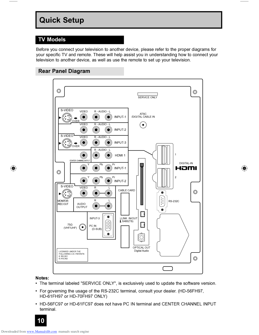
Before you connect your television to another device, please refer to the proper diagrams for your specific TV and remote. These will help assist you in understanding how to connect your television to another device, as well as use the remote to set up your television.
Rear Panel Diagram
SERVICE ONLY
ATSC
OVER
VIDEO R - AUDIO - L
OVER ![]()
R - AUDIO - L
HDMI 1
CENTER CHANNEL INPUT |
|
| |
| Y | Pb | Pr |
|
|
| |
| Y | Pb | Pr |
|
|
| |
| VIDEO | R | L |
CABLE CARD
1
2
MONITOR | AUDIO | R | L |
/RECOUT |
|
| |
| OUTPUT |
|
|
|
|
| |
75Ω |
| PC IN |
|
(VHF/UHF) |
| ||
| |||
|
|
| |
LICENSED UNDER THE FOLLOWING U.S. PATENTS 6,183,091 6,419,362
i.LINK IN/OUT ![]() S400(TS)
S400(TS)
OPTICAL OUT
Digital Audio
Notes:
•The terminal labeled "SERVICE ONLY", is exclusively used to update the software version.
•For governing the usage of the
•
10
Downloaded from www.Manualslib.com manuals search engine
