
RX-D202B, RX-D201S specifications
The JVC RX-D201S and RX-D202B are two high-performance stereo receivers that cater to the needs of audiophiles and casual listeners alike. These models are designed to deliver an immersive audio experience with a range of features and technologies that enhance sound quality and usability.One of the standout features of the JVC RX-D201S and RX-D202B is their impressive power output. Both models deliver solid amplification, ensuring that even the most demanding speakers perform beautifully. The receivers offer a dynamic range that captures the nuances of your favorite music, whether you are listening to classical, rock, or electronic genres. With RMS power ratings that provide ample headroom, these receivers can fill a room with rich, detailed sound.
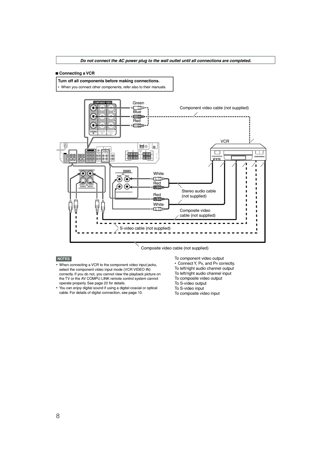
Connectivity is another key aspect of the RX-D201S and RX-D202B. The receivers come equipped with multiple input options, including HDMI, coaxial, optical digital inputs, and analog inputs, allowing users to connect a wide variety of audio and video devices, from Blu-ray players to gaming consoles. The inclusion of Bluetooth technology is a major advantage, enabling wireless streaming from smartphones and tablets. This feature provides added convenience for users who prefer to listen to music without the hassle of wired connections.
The receivers boast a user-friendly interface, making it easy for individuals of all technical backgrounds to navigate through settings and sources. The backlit remote control enhances usability, allowing users to manage their audio experience from across the room.
In terms of audio performance, both models are equipped with advanced sound processing technologies. They support various sound modes, allowing users to tailor the listening experience to their personal preferences. Features such as tone control and equalizer settings further enhance the versatility of the sound output.
The design of the JVC RX-D201S and RX-D202B is sleek and modern, with a minimalist aesthetic that fits well in any home entertainment setup. The built-in cooling system ensures consistent performance even during extended listening sessions, safeguarding the longevity of the unit.
In summary, the JVC RX-D201S and RX-D202B are superb choices for anyone seeking powerful, flexible, and user-friendly stereo receivers. With their robust features, impressive connectivity, and excellent audio quality, they stand out as reliable options in the competitive audio market. Users will find that these receivers excel in delivering a sophisticated listening experience that meets diverse musical tastes and preferences.