2 | CONTROLS AND CONNECTORS |
|
|
|
|
|
|
|
|
|
| |||||||
|
|
|
|
|
|
|
|
|
|
|
|
|
|
|
|
|
| |
| 1 | 6 |
| 7 | 8 | 9 | 10 | 11 |
| 12 13 | 14 | |||||||
|
|
|
|
|
|
|
|
|
|
|
|
|
|
|
|
|
|
|
|
|
|
|
|
|
|
|
|
|
|
|
|
|
|
|
|
|
|
|
|
|
|
|
|
|
|
|
|
|
|
|
|
|
|
|
|
|
2 | 3 | 4 | 5 |
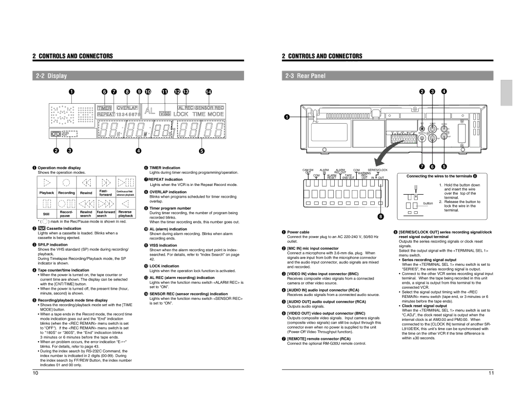
1Operation mode display | 6TIMER indication | ||
Shows the operation modes. | 7Lights during timer recording programming/operation. | ||
|
|
| REPEAT indication |
|
| 8 | Lights when the VCR is in the Repeat Record mode. |
2 CONTROLS AND CONNECTORS
2-3 Rear Panel
1
CAM SW | ALARM | ALARM | COM |
| SERIES/CLOCK | ||||||
OUT | IN | REC OUT |
| WARNING |
| ||||||
| COM |
| ALARM | TAPE |
|
| /REC |
|
| ||
|
|
|
| RESET | END OUT |
| OUT | IN | OUT | ||
2 | 3 | 4 |
|
|
|
|
|
| MIC | VIDEO | AUDIO |
|
|
|
|
|
| IN |
|
|
|
|
|
|
|
|
| IN | IN |
CAM SW | ALARM | ALARM | COM | SERIES/CLOCK | REMOTE |
|
| |
OUT | IN | REC OUT | WARNING |
|
| |||
COM | ALARM | TAPE | /REC | IN OUT |
|
| ||
| RESET END OUT | OUT |
|
|
| |||
|
|
|
|
|
|
|
| OUT |
|
|
|
|
|
|
| OUT |
|
7 | 6 | 5 |
Connecting the wires to the terminals 8 | ||
|
| 1. Hold the button down |
|
| and insert the wire |
Playback Recording | Rewind | Fast- | Continuous field | ||
forward | advance playback | ||||
|
|
| |||
Still | Record- | Rewind | Reverse | ||
|
|
|
| ||
OVERLAP indication Blinks when programs scheduled for timer recording 9overlap.
Timer program number During timer recording, the number of program being
|
|
|
| over the top of the |
|
|
| 2. | terminal. |
| button | Release the button to | ||
|
| lock the wire in the | ||
|
|
|
| |
|
|
|
| |
|
|
|
| terminal. |
|
| pause | search | search | playback |
2 | * ( | ) mark in the Rec/Pause mode is shown in red. | |||
|
| Cassette indication |
|
| |
| Lights when a cassette is loaded. Blinks when a |
| |||
3cassette is being ejected. |
|
| |||
recorded blinks. 0When the timer recording ends, this number goes out.
AL (alarm) indication Shown during alarm recording. Blinks when alarm !recording ends.
8
1Power cable Connect the power plug to an AC
8
[SERIES/CLOCK OUT] series recording signal/clock reset signal output terminal Outputs the series recording signals or clock reset
SP/LP indication Shows the VHS standard (SP) mode during recording/ playback. During Timelapse Recording/Playback mode, the SP 4indicator is shown.
| Tape counter/time indication |
| • When the power is turned on, the tape counter or |
| current time are shown. The display can be selected |
| with the [CNT/TIME] button. |
| • When the power is turned off, the present time (hour, |
5 | minute, second) is shown. |
Recording/playback mode time display • Shows the recording/playback mode set with the [TIME MODE] button. • When a tape ends in the Record mode, the record time mode indication goes out and the "End" indication blinks (when the <REC REMAIN> menu switch is set to "OFF"). If the <REC REMAIN> menu switch is set to "180S" or "360S", the "End" indication blinks 3 minutes or 6 minutes before the tape ends. • When an problem occurs, the error indication
| VISS indication |
| Shown when the alarm recording start point is index- |
| searched. For details, refer to “Index Search” on page |
@ | 42. |
LOCK indication #Lights when the operation lock function is activated.
AL REC (alarm recording) indication Lights when the function menu switch <ALARM REC> is $set to “ON”.
SENSOR REC (sensor recording) indication Lights when the function menu switch <SENSOR REC> is set to “ON”.
[MIC IN] mic input connector Connect a microphone with
[VIDEO IN] video input connector (BNC) Receives composite video signals from a connected 4camera or other video source.
[AUDIO IN] audio input connector (RCA) 5Receives audio signals from a connected audio source.
[AUDIO OUT] audio output connector (RCA) 6Outputs audio signals.
[VIDEO OUT] video output connector (BNC) Outputs composite video signals. Input camera signals (composite video signals) can still be output through this connector even when no power is supplied to the unit
[REMOTE] remote connector (RCA) Connect the optional
signals. Select the output signal with the <TERMINAL SEL 1> menu switch.
•Series recording signal output
When the <TERMINAL SEL 1> menu switch is set to “SERIES”, the series recording signal is output.
•Connect to the other VCR series recording signal input terminal. When the tape being recorded in this unit ends, a signal is output from this terminal to the connected VCR.
•Select the signal output timing with the <REC REMAIN> menu switch (tape end, or 3 minutes or 6 minutes before the tape ends).
•Clock reset signal output
When the <TERMINAL SEL 1> menu switch is set to “C.ADJ”, the clock reset signal is output when the internal clock is at AM0:00 and PM0:00. When connected to the [CLOCK IN] terminal of another SR- L910E/EK, this unit’s time can be synchronised with the time on the other VCR if the time difference is within ±30 seconds.
10 | 11 |