3 | CONNECTIONS |
|
|
3 | CONNECTIONS |
|
|
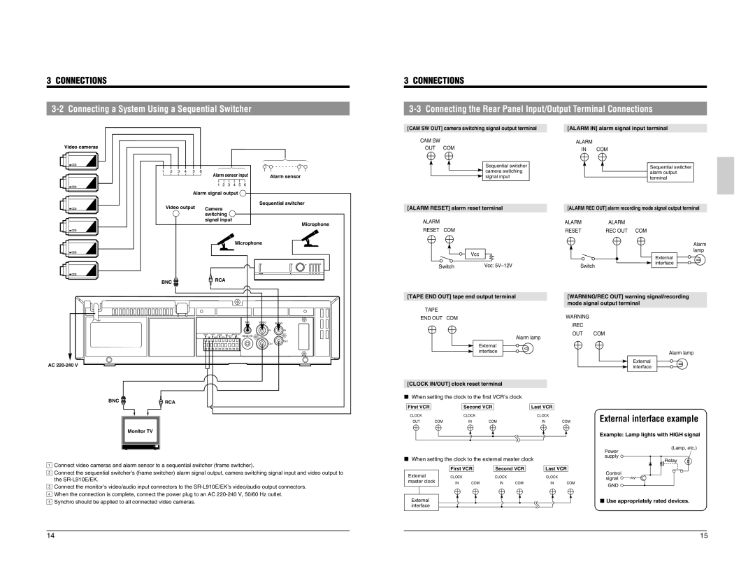
[CAM SW OUT] camera switching signal output terminal
[ALARM IN] alarm signal input terminal |
Video cameras
![]() CCD
CCD
![]() CCD
CCD
123456 |
Alarm sensor input |
123456 |
Alarm signal output |
Alarm sensor
Sequential switcher
CAM SW
OUT COM
Sequential switcher camera switching signal input
ALARM |
|
IN | COM |
Sequential switcher alarm output terminal
![]() CCD
CCD
Video output | Camera |
| switching |
| signal input |
[ALARM RESET] alarm reset terminal
[ALARM REC OUT] alarm recording mode signal output terminal
![]() CCD
CCD
Microphone
ALARM RESET COM
ALARM | ALARM |
RESET | REC OUT COM |
![]() CCD
CCD
![]() CCD
CCD
Microphone
BNC | RCA |
|
![]() Vcc Switch
Vcc Switch
Vcc:
Switch |
Alarm lamp
External interface
[TAPE END OUT] tape end output terminal
TAPE
END OUT COM
[WARNING/REC OUT] warning signal/recording |
mode signal output terminal |
WARNING |
|
|
|
|
|
| MIC | VIDEO | AUDIO |
|
|
|
|
|
| IN |
|
|
|
|
|
|
|
|
| IN | IN |
CAM SW | ALARM | ALARM | COM | SERIES/CLOCK | REMOTE |
|
| |
OUT | IN | REC OUT | WARNING |
|
| |||
COM | ALARM | TAPE | /REC | IN OUT |
|
| ||
| RESET END OUT | OUT |
|
|
| |||
|
|
|
|
|
|
|
| OUT |
|
|
|
|
|
|
| OUT |
|
AC |
|
|
|
|
|
|
|
|
Alarm lamp
External interface
/REC |
|
OUT | COM |
| Alarm lamp |
| External |
| interface |
BNC |
| RCA |
|
| Monitor TV |
21Connect video cameras and alarm sensor to a sequential switcher (frame switcher). | ||
Connect the sequential switcher’s (frame switcher) alarm signal output, camera switching signal input and video output to | ||
3the |
|
|
4Connect the monitor’s video/audio input connectors to the | ||
5When the connection is complete, connect the power plug to an AC | ||
Synchro should be applied to all connected video cameras. | ||
[CLOCK IN/OUT] clock reset terminal |
|
|
| ||||
5 When setting the clock to the first VCR’s clock |
|
| |||||
First VCR |
|
| Second VCR |
| Last VCR |
| |
CLOCK |
|
| CLOCK |
|
| CLOCK |
|
OUT | COM |
| IN | COM |
| IN | COM |
5 When setting the clock to the external master clock |
| ||||||
|
| First VCR | Second VCR | Last VCR | |||
External |
| CLOCK |
| CLOCK |
| CLOCK |
|
master clock | IN | COM | IN | COM | IN | COM | |
External |
|
|
|
|
|
|
|
interface |
|
|
|
|
|
|
|
External interface example
Example: Lamp lights with HIGH signal
(Lamp, etc.) Power
supply ![]()
![]()
![]() Relay
Relay
Control signal ![]()
![]()
![]()
GND ![]()
5 Use appropriately rated devices.
14 | 15 |