11 APPENDIXES |
|
11 APPENDIXES
11-2 Specifications
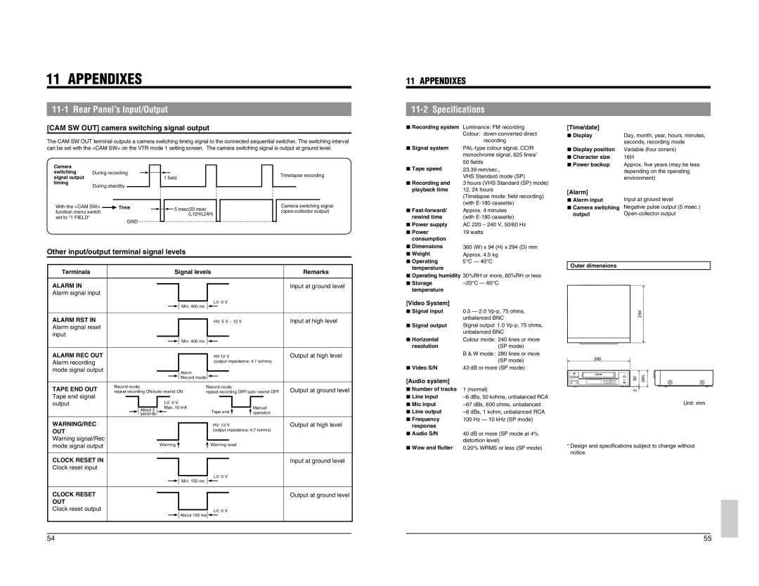
[CAM SW OUT] camera switching signal output |
| ||||||||||||
The CAM SW OUT terminal outputs a camera switching timing signal to the connected sequential switcher. The switching interval | |||||||||||||
can be set with the <CAM SW> on the VTR mode 1 setting screen. The camera switching signal is output at ground level. | |||||||||||||
Camera |
|
|
|
|
|
|
|
|
|
|
|
|
|
switching | During recording |
|
|
|
|
|
|
|
|
| Timelapse recording | ||
|
|
|
|
|
|
|
|
| |||||
signal output |
|
|
|
|
|
|
|
| 1 field | ||||
|
|
|
|
|
|
|
|
| |||||
timing | During standby |
|
|
|
|
|
|
|
|
|
| ||
|
|
|
|
|
|
|
|
|
|
| |||
With the <CAM SW> |
| Time |
|
|
|
|
|
|
|
| 5 msec/20 msec | Camera switching signal | |
|
|
|
|
|
|
|
|
| |||||
function menu switch |
|
|
|
|
|
|
|
|
|
| (L12H/L24H) | ||
set to "1 FIELD" |
|
|
|
|
|
|
|
|
|
|
|
| |
|
| GND |
|
|
|
|
|
|
|
|
|
| |
|
|
|
|
|
|
|
|
|
|
|
|
| |
5 Recording system |
5 Signal system |
5 Tape speed |
5 Recording and |
playback time |
5 |
rewind time |
5 Power supply |
5 Power |
consumption |
Luminance: FM recording Colour:
[Time/date] |
|
5 Display | Day, month, year, hours, minutes, |
| seconds, recording mode |
5Display position Variable (four coners)
5 Character size | 16H |
5Power backup Approx. five years (may be less depending on the operating environment)
[Alarm] |
|
5 Alarm input | Input at ground level |
5Camera switching Negative pulse output (5 msec.)
output |
Other input/output terminal signal levels | |
Terminals | Signal levels |
Remarks
5 Dimensions |
5 Weight |
5 Operating |
temperature |
360 (W) x 94 (H) x 294 (D) mm Approx. 4.5 kg 5°C — 40°C
Outer dimensions
ALARM IN |
|
|
|
|
|
|
|
Alarm signal input |
|
|
|
|
|
|
|
ALARM RST IN |
|
| Min. 400 ms |
| LV: 0 V | ||
|
|
|
|
| |||
|
| HV: 5 V ~ 12 V | |||||
|
|
|
| ||||
Alarm signal reset |
|
|
|
|
|
|
|
input |
|
|
|
|
|
|
|
|
|
| Min. 400 ms |
|
|
|
|
|
|
| |||||
|
|
|
|
|
|
|
|
Input at ground level
Input at high level
5Operating humidity 30%RH or more, 80%RH or less
5 Storage |
|
temperature |
|
[Video System] |
|
5Signal input 0.5 — 2.0
5Signal output Signal output 1.0
5 Horizontal | Colour mode: 240 lines or more |
resolution | (SP mode) |
294
ALARM REC OUT Alarm recording mode signal output
HV:12 V |
(output impedance: 4.7 kohms) |
Alarm |
Output at high level
| B & W mode : 280 lines or more |
| (SP mode) |
5 Video S/N | 43 dB or more (SP mode) |
360
TAPE END OUT Tape end signal output
WARNING/REC OUT Warning signal/Rec mode signal output
Record mode: |
|
|
|
|
|
| Record mode |
|
|
|
|
|
|
|
|
| |
|
|
|
|
|
| Record mode: |
|
| |||||||||
|
|
|
|
|
|
|
|
| |||||||||
repeat recording ON/auto rewind ON | repeat recording OFF/auto rewind OFF | ||||||||||||||||
|
|
| LV: 0 V |
|
|
|
|
|
|
|
|
| |||||
|
|
|
|
|
|
|
|
|
|
|
| ||||||
| About 2 |
| Max. 10 mA |
|
|
|
|
|
|
| Manual | ||||||
|
|
|
|
| Tape end |
| |||||||||||
| seconds |
|
|
|
|
|
|
|
|
|
|
| operation | ||||
|
|
|
|
|
|
|
|
|
|
|
| HV: 12 V |
|
| |||
|
|
|
|
|
|
|
|
|
|
|
| (output impedance: 4.7 kohms) | |||||
|
| Warning |
|
|
|
| Warning reset |
|
| ||||||||
Output at ground level
Output at high level
[Audio system]
5Number of tracks
5Line input
5Mic input
5Line output
5Frequency response
5Audio S/N
5Wow and flutter
1 (normal)
40 dB or more (SP mode at 4% distortion level) 0.20% WRMS or less (SP mode)
92 | (94) |
2 |
|
Unit: mm
* Design and specifications subject to change without notice.
CLOCK RESET IN |
|
|
|
|
|
|
|
Clock reset input |
|
|
|
|
|
|
|
CLOCK RESET |
|
| Min. 150 ms |
| LV: 0 V | ||
|
|
|
|
|
| ||
|
|
| |||||
|
|
|
|
|
|
| |
OUT |
|
|
|
|
|
|
|
Clock reset output |
|
|
|
| LV: 0 V | ||
|
|
| About 150 ms |
|
|
| |
|
|
|
|
|
|
|
|
Input at ground level
Output at ground level
54 | 55 |