JVC TK-C1431 manual Simplex, Int/Gl, Duplex, Not Used

Models: TK-C1431

1 22
Download 22 pages 3.64 Kb
Page 6
Image 6

INTRODUCTION

Controls, Connectors and Indicators (Continued)

13

[ , , , ] Up-and-down, left-and-


right Button


These buttons select items on the menu


screen and change a set value.


( Page 23)

14

[EXT.TERM-ON/OFF] Terminal On/Off


Switch of External Synchronization


Signal


This is a terminating ON/OFF switch for


the external synchronization input signal.


When this is switched ON, termination is


executed via a 75 1 resistor.


ON: terminates at 751.


OFF: does not terminate at 751.


(ON: At time of factory shipment)

15

[INT/GL, LL] Selector Switch for

SIMPLEX:

This switch sets to SIMPLEX when the transmission between the camera and a remote control unit is in a simplex system (one-way).

(DUPLEX: At time of factory shipment)

17 [RX.TERM-ON/OFF] RX SignalTerminal

ON/OFF Switch

This sets whether or not the signal

between RX + and RX – on the back 20

should be terminated at the value of

1101 resistance.

ON: Terminated.

OFF: Not terminated.

If the system including the camera is the

M.DROP (Multi-drop, RS-485) system,

only the last camera mounted along the


(


)


+

-


1

2


DC12V

AC24V

CLASS 2 ONLY(U TYPE)

TX+ TX- RX+ RX- AUX GND

ISOLATEDPOWERONLY TYPE)(E

B

C

D


A


Y/C OUT


SYNC IN

VIDEO OUT


SEE INST-

POWER


RUCTION


MANUAL

TK-C1430E

¤


) ⁄


TX+ TX- RX+ RX- AUX GND


A B C D


Y/C OUT


SYNC IN

VIDEO OUT


SEE INST-


RUCTION

POWER

MANUAL

TK-C1431EG ¤

Synchronizing System

This switch sets the synchronizing system

for the camera.

INT/GL:

This is set for internal synchronization

(INT) or external synchronization (GL).

LL (Line Lock):

The camera’s vertical synchronization is locked to the AC power line frequency. When switching between multiple cameras using a switcher, selecting this mode and adjusting the vertical phase can reduce the monitor sync disturbances occur that when the camera image is switched. (This cannot be used in regions where the power frequency is 60 Hz) (INT/GL: At time of factory shipment)

16[DUPLEX, SIMPLEX] Selector Switch for Transmission System

If the setting is changed, be absolutely sure to switch on the power again.

DUPLEX:

This switch sets to DUPLEX when the transmission between the camera and a remote control unit is in a duplex system (two-way).

control signal cable is set to “ON” and

the other cameras are set to “OFF”. In

case of the M.DROP system, it becomes

necessary to set the Machine ID. ( Page

35)

If the system including the camera is the

P TO P (Point to Point, RS-422A) system,

set this switch of all the cameras to “ON”.

The item STYLE on the COMMUNICA-

TION screen sets M.DROP or P TO P

( Page 35)

(ON: At time of factory shipment)

18 NOT USED

This cannot be used. Do not switch.

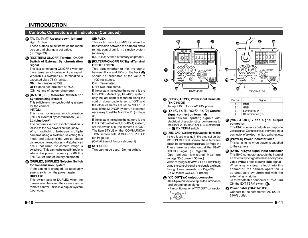
19[DC 12V, AC 24V] Power input terminals (TK-C1430E)

To input DC 12V or AC 24V power.

20[TX+A, TX-B, RX+C, RX-D] Control signal connection terminals Terminals for inputting signals with electrical characteristics conforming to the EIA/TIA RS-422A or RS-485 standard.  17 RX.TERM switch

21[AUX, GND] Auxiliary Input/Output Terminals

If there is any change in the area set on the MOTION DETECT screen, these terminals output the corresponding signals.( Page 34) These terminals also output the B&W/ COLOUR signal. ( Page 30)

[Open-collector low signal. Maximum voltage 30V, current 30mA.]

When carrying out B&W/COLOUR switching using the control signal, the signals are input through these terminals. ( Page 30)

[B&W: make; COLOUR: break]

22[Y/C OUT] Y/C output connector

This 4-pin connector outputs the luminance and chrominance signal.

Pin configuration of Y/C OUT connector

4 3

2 1

Pin No.

Signal

1GND

2GND

3Luminance (Y)

4Chrominance (C)

23 [VIDEO OUT] Video signal output connector

This BNC connector outputs a composite video signal. Connect this to the video input connector of a video monitor, switcher, etc.

24[POWER] Power indicator lamp

This lamp lights when power is supplied to the camera.

25[SYNC IN] Sync signal input connector This BNC connector accepts the input of an external sync signal such as a composite video (VBS) or black burst (BB) signal. When a sync signal is input into this connector, the camera operation is automatically synchronized with the external sync signal.

To terminate this connector at 751, turn ON the EXT.TERM switch 14 .

26Power cable (TK-C1431EG)

Connect to the commercial AC (220V – 240V) outlet.

E-10


E-11


Page 6
Image 6
JVC TK-C1431 manual Simplex, Int/Gl, Duplex, Not Used

TK-C1431 specifications

The JVC TK-C1431 is a high-performance CCTV camera designed for professional surveillance applications. Its compact design and versatile features make it an excellent choice for various environments, including retail, transportation, and public spaces. This camera is known for delivering exceptional image quality and reliable performance in diverse lighting conditions.

One of the main features of the TK-C1431 is its advanced CCD sensor, which ensures crisp and clear image capture. The camera provides a resolution of 540 TV lines, allowing for detailed surveillance footage. Its sensitivity rating is notable, with a low-light performance of 0.05 lux at F1.2, enabling it to produce usable images even in dimly lit conditions. This feature is crucial for security professionals who require reliable performance around the clock, regardless of the lighting environment.

The TK-C1431 also integrates JVC's proprietary Image Stabilization Technology, which minimizes the effects of vibrations or movement that could compromise image quality. This technology is especially useful in dynamic environments where the camera may be subjected to external disturbances, such as wind or nearby traffic. As a result, users can expect stable and clear images even in less-than-ideal scenarios.

Moreover, the camera offers versatile installation options, thanks to its adjustable mounting options. Users can mount it on walls or ceilings, accommodating various surveillance needs. The TK-C1431 also features a varifocal lens, allowing for adjustable focal lengths ranging from 3.8mm to 9.5mm. This flexibility provides security personnel with the ability to zoom in on specific areas or objects, enhancing their monitoring capabilities.

Additionally, the JVC TK-C1431 supports various video output formats, including composite video output, making it compatible with a wide range of DVRs and monitoring systems. Its robust build quality ensures reliability in challenging environments, featuring a weather-resistant housing that allows for outdoor installation.

With these advanced features, technologies, and characteristics, the JVC TK-C1431 stands out as a reliable and effective option in the field of surveillance cameras. Whether for a small business or larger security operations, its combination of high-quality imaging, adaptability, and rugged design makes it an excellent choice for enhancing security systems. The TK-C1431 is an investment in peace of mind, providing surveillance solutions that meet the demands of today’s security challenges.