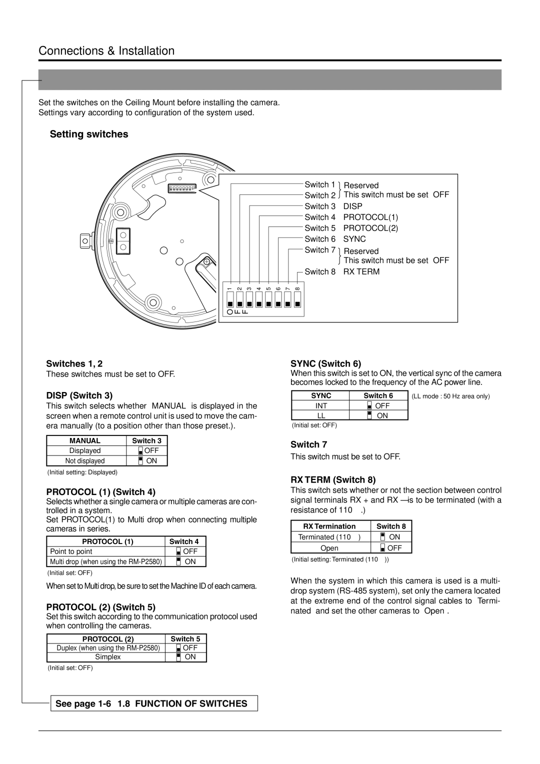
TK-C676 specifications
The JVC TK-C676 is a professional-grade CCTV camera renowned for its impressive image quality and reliable performance in various surveillance applications. As part of JVC's reputable line of security products, the TK-C676 incorporates advanced technologies that make it a popular choice among security professionals and businesses alike.One of the standout features of the TK-C676 is its high-resolution imaging capability. With a 1/3-inch CCD sensor, this camera delivers crisp and clear images, ensuring optimal visibility even in challenging lighting conditions. The camera offers a resolution of 540 TV lines, which allows for detailed surveillance footage that can be crucial for identifying individuals or activities in monitored areas.
Another notable characteristic of the TK-C676 is its robust low-light performance. Thanks to its sense-up technology, the camera can automatically adjust its sensitivity in low-light environments, providing better image quality without the need for external lighting. This feature is particularly valuable for nighttime surveillance or in dimly lit indoor settings, enhancing the overall effectiveness of security measures.
The TK-C676 also excels in flexibility and adaptability with its mechanical IR cut filter. This technology allows for seamless switching between day and night modes, ensuring consistent image quality during both daytime and nighttime operation. This adaptability makes the camera suitable for various applications, including retail stores, parking lots, and public spaces.
Additionally, the JVC TK-C676 features a varifocal lens with a focal length of 3.5mm to 8mm, providing users with the ability to adjust the field of view based on specific surveillance needs. This versatility enables the camera to cover wide areas or focus on particular subjects, making it ideal for both indoor and outdoor placements.
In terms of durability, the TK-C676 is built to withstand harsh environmental conditions. With a sturdy housing that resists both water and dust, this camera can be installed in various locations without compromising on performance. This reliability is essential for continuous operation in demanding environments.
Overall, the JVC TK-C676 is a well-rounded CCTV camera that offers high-resolution imaging, excellent low-light performance, and adaptable features. Its combination of advanced technology, durable construction, and flexible camera options makes it a strong choice for anyone seeking a reliable surveillance solution. Whether for commercial, industrial, or residential applications, the TK-C676 proves to be a valuable asset in enhancing security measures.

