English
B. System Operation
HD 4000 C / HD 6000 C
1. Operating Controls
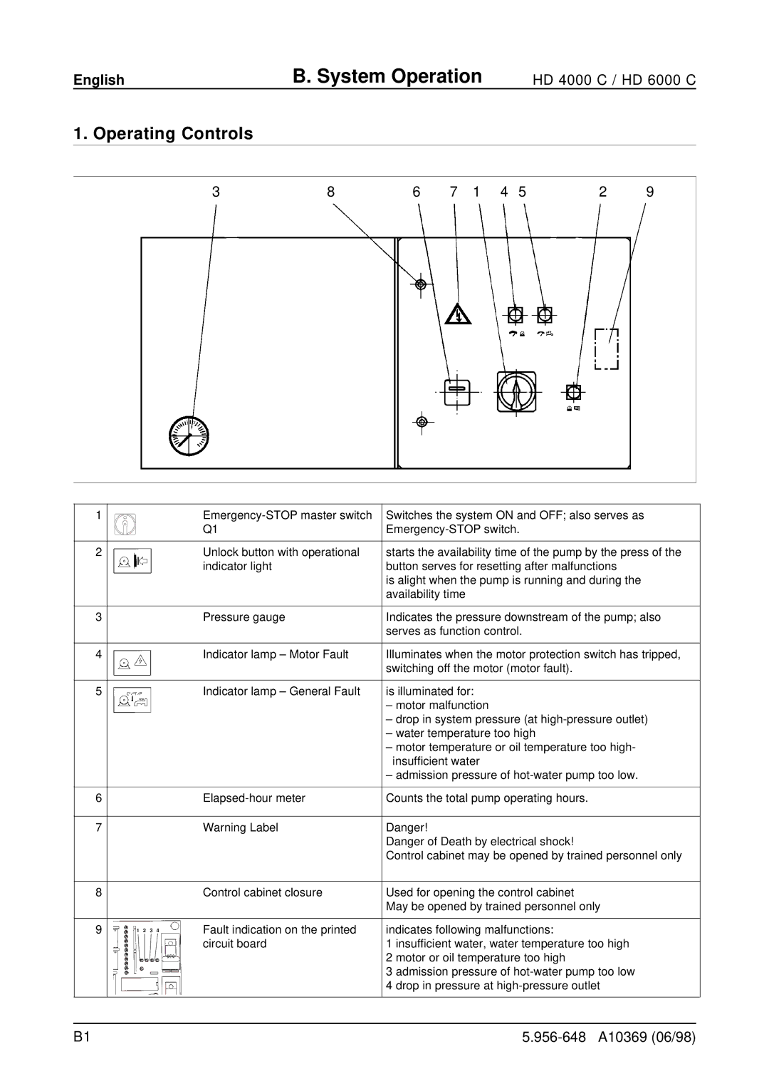
3 | 8 | 6 | 7 | 1 | 4 | 5 | 2 | 9 |
1 |
| Switches the system ON and OFF; also serves as | |
|
| Q1 | |
2 |
| Unlock button with operational | starts the availability time of the pump by the press of the |
|
| indicator light | button serves for resetting after malfunctions |
|
|
| is alight when the pump is running and during the |
|
|
| availability time |
3 |
| Pressure gauge | Indicates the pressure downstream of the pump; also |
|
|
| serves as function control. |
4 |
| Indicator lamp – Motor Fault | Illuminates when the motor protection switch has tripped, |
|
|
| switching off the motor (motor fault). |
5 |
| Indicator lamp – General Fault | is illuminated for: |
|
|
| – motor malfunction |
|
|
| – drop in system pressure (at |
|
|
| – water temperature too high |
|
|
| – motor temperature or oil temperature too high- |
|
|
| insufficient water |
|
|
| – admission pressure of |
6 |
| Counts the total pump operating hours. | |
7 |
| Warning Label | Danger! |
|
|
| Danger of Death by electrical shock! |
|
|
| Control cabinet may be opened by trained personnel only |
8 |
| Control cabinet closure | Used for opening the control cabinet |
|
|
| May be opened by trained personnel only |
9 | 1 2 3 4 | Fault indication on the printed | indicates following malfunctions: |
|
| circuit board | 1 insufficient water, water temperature too high |
|
|
| 2 motor or oil temperature too high |
|
|
| 3 admission pressure of |
|
|
| 4 drop in pressure at |
B1 |
