F
Assembly
![]() WARNING
WARNING
Children can be harmed by small parts, sharp edges and sharp points
in the vehicle’s unassembled state, or by electrical items. Care should be taken in unpacking and assembly of the vehicle. Children should not handle parts, including the battery, or help in assembly of the vehicle.
1 |
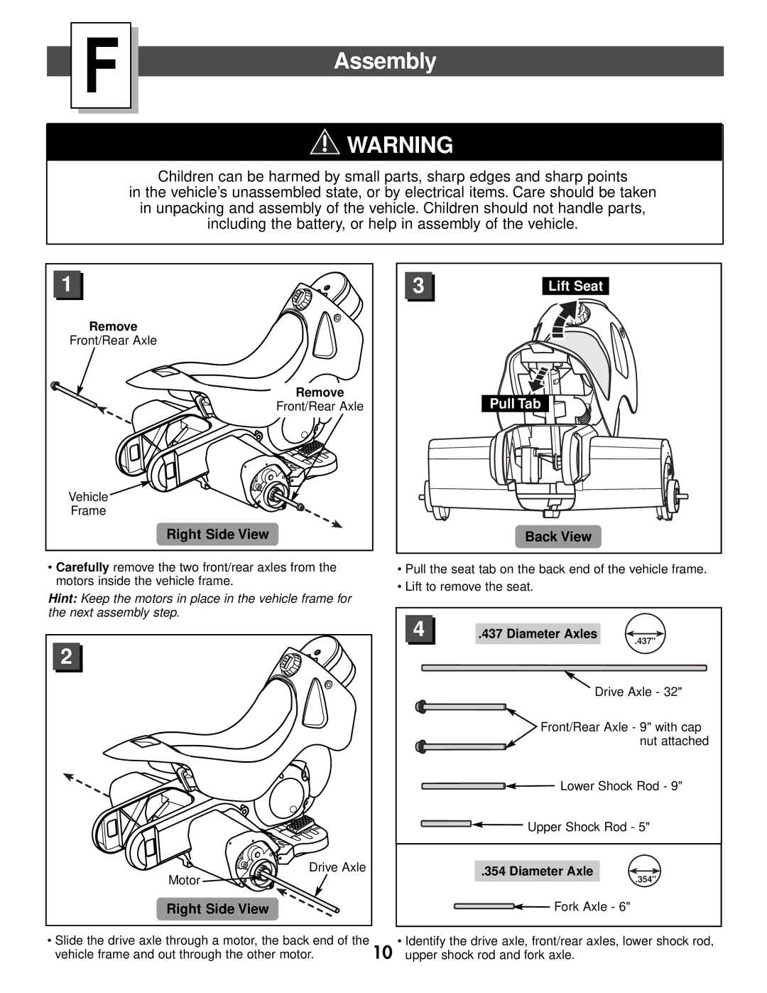
Remove |
Front/Rear Axle |
Remove |
Front/Rear Axle |
Vehicle |
Frame |
Right Side View |
•Carefully remove the two front/rear axles from the motors inside the vehicle frame.
Hint: Keep the motors in place in the vehicle frame for the next assembly step.
2 |
Drive Axle |
Motor |
Right Side View |
3 | Lift Seat |
| Pull Tab |
| Back View |
•Pull the seat tab on the back end of the vehicle frame.
•Lift to remove the seat.
4 | .437 Diameter Axles |
| .437" |
| Drive Axle - 32" |
| Front/Rear Axle - 9" with cap |
| nut attached |
| Lower Shock Rod - 9" |
| Upper Shock Rod - 5" |
.354 Diameter Axle
.354"
![]()
![]() Fork Axle - 6"
Fork Axle - 6"
• Slide the drive axle through a motor, the back end of the | 10 | • Identify the drive axle, front/rear axles, lower shock rod, |
vehicle frame and out through the other motor. | upper shock rod and fork axle. |