Installation InstructiOns (cdnt'd)

Temperature-Pressure Relief Vave

AWARNING

At the time of manufacturethis water heater was provided with a combinationtemperetum-pressuresreliefvalvecertified _" a nationally.recognizedtesting I.aboratorythat maintains

._riodlcinspectionof productionof hstedequipmentor mate- rials, as meeting the requirements for Relief Valves and

AutomaticGas ShutoffDevicesfor Hot Water SupplySystems, and the latest edition of ANSI Z21.22 and the code require- mentsof ASME. If replaced,the valvemustmeet the require- mentsof localcodes,but not lessthan a combinationtempera- ture and pressurerelief valvecertifiedas meodngthe require- mentsfor ReliefValvesand AutomaticGas ShutoffDevicesfor Hot Water SupplySystems,ANSI 7-21.22bya nationally recog- nized tesdnglaboratorythat maintains periodicinspectionof

productionof listedequipment or maten.'als.

The valve mustbe m_(ed with a maxmmumset pressurenot to exceed the marked hydrostaticworking pressure of the water heater (150 IbsJsqin. .) and a dischargecapacitynot less than the water heater input r_e asshownon the modelrating plate. (Electric heaters - watts dividedby 1000 x 3415 equal BTU/Hr. rate.)

Yourlocaljurisdictionalauthority, whitemand_ingthe useof a temperature-pressurereliefwdve complyingwith ANSI Z21.22

and ASME, may require a valvemodel differentfrom the one fornished with the water heater.

Compliancewith suchlocalrequirementsmust be satisfiedby the installeror end useroftbe water heater with a locallypre- scribedtemperature-pressurereliefvalveinstalled in the deslg-

natod openingin the water heater in placeof the factory fur- nishedvalve.

For safeoperationofthe water heater,the reliefvalvemust not be removed from it'sdesignatedopeningor plugged.

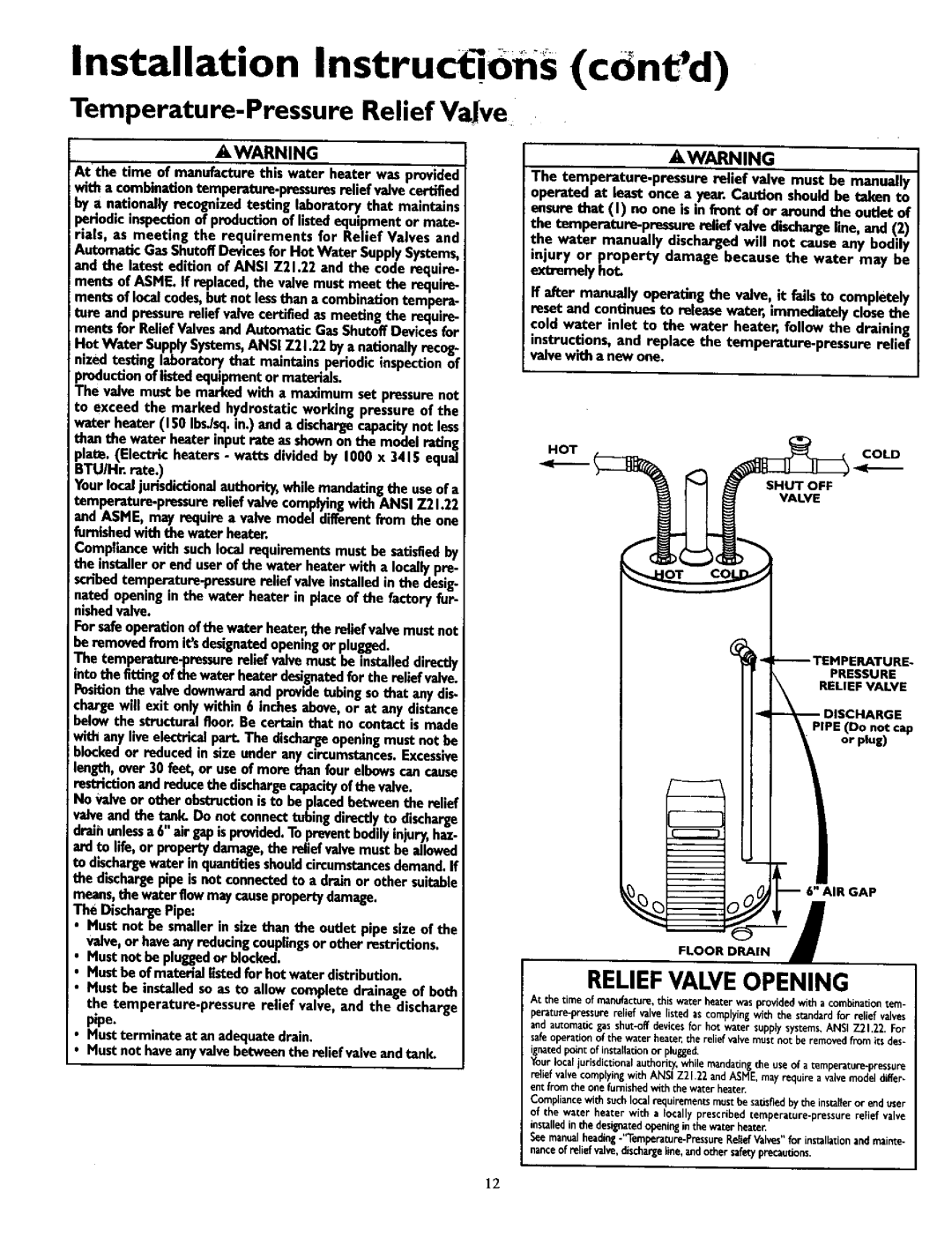
The temperature.pressurereliefvalvemustbe installeddirectly

intothe flying of thewater heaterdesignatedfor the reliefvalve. Positionthe valvedownwardand providetubingsothat any dis- chargewill exit onlywithin 6 inchesabove,or at any distance belowthe structuralfloor.Be certainthat no contact is made

!with any ve e ec_ical part. The dschargeopenng mustnot be

i blockedor reducedin sizeunder any circumstancesExcessive. length,over30 feet,or useof more than fourelbowscancause restriction andreducethe dischargecapacityofthe valve.

No Valveor otherobstructionisto be placedbetweenthe relief

valveand the tank. Do not connecttubingdirectlyto discharge dralhunlessa 6"air gapisprovidedTopreventbodilyinlury,. haz-

ardto life, or propertydamage,the raliefvalvemustbe allowed to dischargewater in quantitiesshouldcircumstancesdemand.If the dischargepipeisnot connectedto a drain or other suitable means,the waterflowmaycausepropertydamage.

The DischargePip_

Must not be smallerin sizethan the outlet pipe size of the valve,or haveany reducingcouplingsor other restrictions.

Must not be pluggedor blocked.

Mustbe of materiallistedfor hot waterdistribution.

Must be installedsoas to allow completedrainageof both the temperature-pressure relief valve, and the discharge pipe.

Mustterminateat anadequatedrain.

Mustnot haveanyvalvebetweenthe relief valveand tank.

A,WARNING

The temperature.pressure relief valve must be manually operated at least once a yea_ C_udon shouldbe taken to ensurethat (I) no one is in front of or aroundthe outlet of

the temperatum-preasure relief valvedischargeline, and (2) the water manually dischargedwill not causeany bodily

injury or property damage because the water may be extxemelyhot.

ffafter manually operating the valve, it failsto completely reset and continues to releasewater, immediatelyclosethe cold water inlet to the water heater, follow the draining

instructions, and replace the temperature-pressure relief

valve with a new one.

HO _T

COLD


SHUT OFF


VALVE

r- --TEMPERATURE-

PRESSURE

RELIEF VALVE

_t-_DISCHARGE

PIPE (Do not cap

or plug)

!

6" AIR GAP

FLOOR DRAIN i

RELIEFVALVE OPENING

At the time of manufacture,this water heater was provided with a combinationtern-

perature-pressure relief valve listed as complying with the standard for relief valves and automatic gas shut-off devicesfor hot water supply systems,ANSI Z21.22. For safeoperation of the water heaten the relief valve must not be removed from its des-

ignatedpoint of installationor plugged.

Your local jurisdictional authority, while mandatingthe use of a temperature-pressure

relief valve complyingwith ANSI Z2h22 and ASME, may require a valve model differ- ent from the one furnished with the water heater.

Compliancewith such local requirements must be satisfied by the instaberor end user of the water beater with a locally prescribed temperature-pressure reFief valve installedin the designated opening in the water heate_

See manual heading.'%mperature-Pressure Relief Valves"for installationand maint_

nance of relief valve,discharge line, andother safetyprecautions.

12

Page 12
Image 12
Kenmore 153.330451, 153.330501, 153.330751, 153.3304OI Installation InstructiOns cdntd, Temperature-Pressure Relief Vave

153.3304OI, 153.330551, 153.330451, 153.330751, 153.330701 specifications

The Kenmore 153 series of dehumidifiers, including models 153.330501, 153.330701, 153.330451, 153.330751, and 153.330551, represent a versatile lineup designed to tackle moisture control in residential spaces. These dehumidifiers are essential appliances for maintaining optimal humidity levels, which can contribute to improved air quality and comfort in homes, especially in areas prone to dampness.

One of the main features of the Kenmore 153 series is their considerable moisture removal capacity. These models are engineered to effectively extract moisture from the air, with capacities ranging from 30 to 70 pints per day, allowing them to handle spaces of various sizes from small rooms to larger basements. This makes them ideal for both typical home environments and more humid settings.

Technologically, the Kenmore 153 series includes advanced humidistats that allow for precise humidity control. This feature enables users to set their desired humidity levels, ensuring that the dehumidifier operates only when necessary, helping to save on energy costs. The series also includes built-in continuous drainage options, which can be a convenient solution for prolonged use, eliminating the need to frequently empty the water tank.

Another noteworthy characteristic is their user-friendly interface. Most models in this series feature digital displays for easy monitoring, along with simple controls that make adjusting settings straightforward. This focus on usability is complemented by quiet operation, ensuring that the dehumidifiers can run unobtrusively in the background without causing significant noise disruption.

Energy efficiency is a crucial aspect of the Kenmore 153 line, as the models are designed to meet Energy Star standards. This means they consume less energy while delivering effective performance, making them an environmentally friendly choice in moisture management.

Additionally, these models often come equipped with features such as washable filters that help to reduce airborne allergens and ensure cleaner air. This is particularly beneficial for individuals with allergies or respiratory issues, creating a healthier indoor environment.

In summary, the Kenmore 153.330501, 153.330701, 153.330451, 153.330751, and 153.330551 dehumidifiers combine powerful moisture removal capabilities with advanced technologies, user-friendly features, and energy efficiency. They are a valuable investment for any homeowner looking to improve air quality and combat humidity-related issues effectively.