Piping Installation

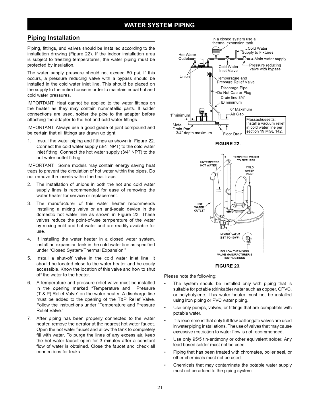
Piping, fittings, and valves should be installed according to the installation drawing (Figure 22). If the indoor installation area is subject to freezing temperatures, the water piping must be protected by insulation.

The water supply pressure should not exceed 80 psi. If this occurs, a pressure reducing valve with a bypass should be installed in the cold water inlet line. This should be placed on the supply to the entire house in order to maintain equal hot and cold water pressures.

IMPORTANT: Heat cannot be applied to the water fittings on the heater as they may contain nonmetallic parts. If solder connections are used, solder the pipe to the adapter before attaching the adapter to the hot and cold water fittings.

IMPORTANT: Always use a good grade of joint compound and be certain that all fittings are drawn up tight.

1.Install the water piping and fittings as shown in Figure 22. Connect the cold water supply (3/4" NPT) to the cold water inlet fitting. Connect the hot water supply (3/4" NPT) to the hot water outlet fitting.

IMPORTANT: Some models may contain energy saving heat traps to prevent the circulation of hot water within the pipes. Do not remove the inserts within the heat traps.

2.The installation of unions in both the hot and cold water supply lines is recommended for ease of removing the water heater for service or replacement.

3, The manufacturer of this water heater recommends installing a mixing valve or an anti-scald device in the domestic hot water line as shown in Figure 23. These valves reduce the point-of-use temperature of the water by mixing cold and hot water and are readily available for use.

4, If installing the water heater in a closed water system, install an expansion tank in the cold water line as specified under "Closed System/Thermal Expansion."

5, Install a shut-off valve in the cold water inlet line. It should be located close to the water heater and be easily accessible. Know the location of this valve and how to shut off the water to the heater.

6, A temperature and pressure relief valve must be installed

in the opening marked "Temperature and Pressure (T & P) Relief Valve" on the water heater. A discharge line must be added to the opening of the T&P Relief Valve.

Follow the instructions under "Temperature and Pressure Relief Valve."

7, After piping has been properly connected to the water heater, remove the aerator at the nearest hot water faucet. Open the hot water faucet and allow the tank to completely fill with water. To purge the lines of any excess air, keep the hot water faucet open for 3 minutes after a constant flow of water is obtained. Close the faucet and check all connections for leaks.


In a closed system use a


thermal

expansion

tank


Water


Hot Water


to

Fixtures


'_


L_Pressure


reducin_ ply


Cold

Water


Inlet

Valve


valve

with

bypass


3erature

and


Pressure

Relief

Valve


Discharge

Pipe


'---Do Not

Cap

or

Plug


Drain

line

3/4"


_/.ID

minimum


6" Maximum


l"minimum

*-l I_

"_

i--Air Gap


u___[


IMassachussetts:


Metal

t _r

/=


I Install

a vacuum

relief

I

V

_


lin cold

water

line

per

I

Drain

Pan


Isect_°n19 MGL


I

1 314" depth

maximum

_Xgloor

Drain

142.

FIGURE 22.

TO FIXTURES

UNTEMPERED

HOT WATER

COLD

WATER

INLET

HOT

OUTLET

\

MIXING VALVE

(SET TO 120°F)

FOLLOW THE MIXING

VALVE MANUFACTURER'S

INSTRUCTIONS

FIGURE 23.

Please note the following:

The system should be installed only with piping that is suitable for potable (drinkable) water such as copper, CPVC, or polybutytene. This water heater must not be installed using iron piping or PVC water piping.

Use only pumps, valves, or fittings that are compatible with potable water.

It is recommend that only full flow ball or gate valves are used

in water piping installations. The use of valves that may cause excessive restriction to water flow is not recommended.

Use only 95/5 tin-antimony or other equivalent solder. Any lead based solder must not be used.

Piping that has been treated with chromates, boiler seal, or other chemicals must not be used.

Chemicals that may contaminate the potable water supply must not be added to the piping system.

21

Page 21
Image 21
Kenmore 153.33114, 153.33115 manual Piping Installation, Isectn 19 MGL, Lminimum

153.33114, 153.33115 specifications

The Kenmore 153.33115 and 153.33114 are high-efficiency dehumidifiers designed to effectively manage moisture levels in residential spaces, providing comfort and safeguarding homes against the damaging effects of excess humidity. Both models embody Kenmore's commitment to quality, innovative technologies, and user-friendly features, making them ideal choices for maintaining optimal indoor air quality.

One of the standout features of the Kenmore 153.33115 and 153.33114 is their powerful dehumidification capability. With the capacity to remove up to 70 pints of moisture per day, these dehumidifiers efficiently tackle dampness in areas of up to 1,500 square feet. This makes them suitable for various spaces, including basements, laundry rooms, and even larger living areas, ensuring a healthy environment free from mold and mildew growth.

The models are equipped with an adjustable humidistat, which allows users to set their desired humidity levels easily. This feature not only enhances user control but also ensures energy efficiency by allowing the machines to operate only when necessary. Alongside energy efficiency, these dehumidifiers are designed to comply with Department of Energy guidelines, making them an eco-friendly choice.

Both models also feature a continuous drainage option, enabling hassle-free operation without the need for constant manual emptying of the water tank. When the water tank reaches capacity, an automatic shut-off function prevents overflow, ensuring peace of mind for users.

In terms of convenience, the Kenmore 153.33115 and 153.33114 have a user-friendly digital control panel with an easy-to-read LED display. This intuitive interface makes it simple to adjust settings, check humidity levels, and monitor overall performance. Additionally, the inclusion of wheels and a lightweight design enhances portability, allowing users to move the dehumidifiers where they are needed most.

Another notable aspect is the enhanced air filtration system. These dehumidifiers come with a removable, washable filter that effectively captures dust, allergens, and other airborne particles, contributing to better indoor air quality.

In conclusion, the Kenmore 153.33115 and 153.33114 are exemplary dehumidifiers that combine efficient moisture removal, user-friendly features, and eco-conscious designs. With their robust performance, effective humidity control, and added convenience features, these models stand out as reliable solutions for maintaining a comfortable and healthy indoor environment.