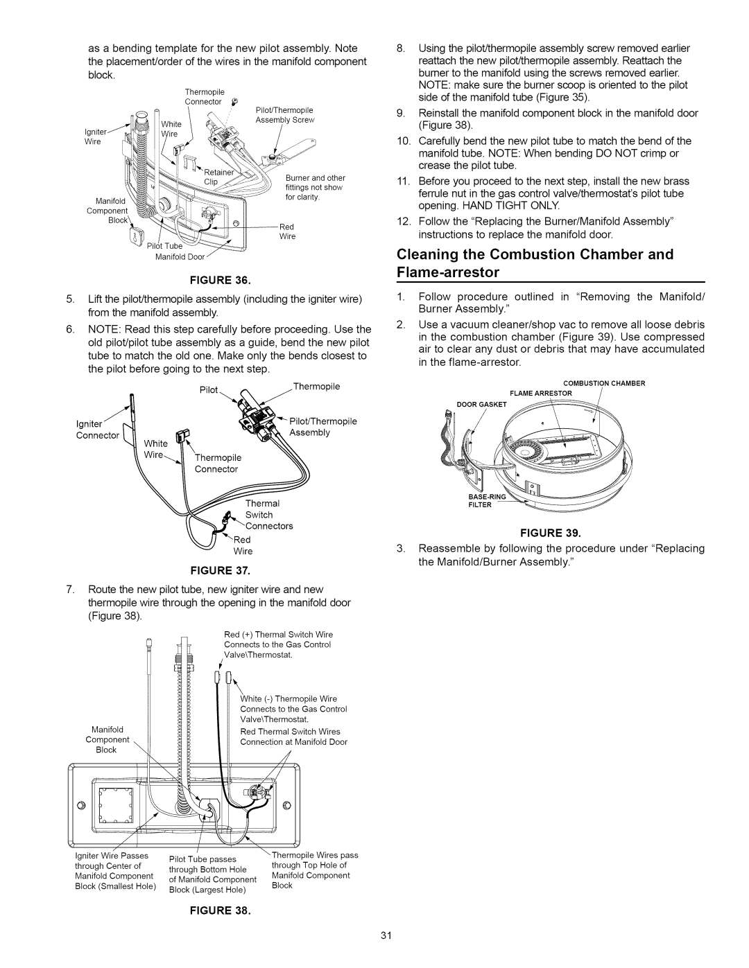
asabendingtemplateforthenewpilotassemblyNote.

theplacement/orderofthewiresinthemanifoldcomponent

block.

Thermopile

Connector _e

Pitot/Thermopite

Assembly Screw

Igniter j_-

Wire i%'


Burneran other

Mantfot!

:_?_i_

fittingsnotshow


_;':_

for clarity.

Component


Block_

--

Red


Wire

8.Using the pilot/thermopite assembly screw removed earlier reattach the new pitot/thermopite assembly. Reattach the bumer to the manifold using the screws removed earlier. NOTE: make sure the burner scoop is oriented to the pilot side of the manifold tube (Figure 35).

9.Reinstall the manifold component block in the manifold door (Figure 38).

10.Carefully bend the new pilot tube to match the bend of the manifold tube. NOTE: When bending DO NOT crimp or crease the pilot tube.

11.Before you proceed to the next step, install the new brass

ferrule nut in the gas control valve/thermostat's pilot tube opening. HAND TIGHT ONLY.

12.Follow the "Replacing the Burner/Manifold Assembly" instructions to replace the manifold door.

FIGURE 36.

5, Lift the pitot/thermopite assembly (including the igniter wire) from the manifold assembly.

6.NOTE: Read this step carefully before proceeding. Use the old pilot/pilot tube assembly as a guide, bend the new pilot tube to match the old one. Make only the bends closest to the pilot before going to the next step.

_ile

pile

Connector

Assembly

Thermal

Switch

Wire

FIGURE 37.

7, Route the new pilot tube, new igniter wire and new thermopite wire through the opening in the manifold door (Figure 38).

Cleaning the Combustion Chamber and Flame-arrestor

1, Follow procedure outlined in "Removing the Manifold/ Burner Assembly."

2.Use a vacuum cleaner/shop vac to remove all loose debris in the combustion chamber (Figure 39). Use compressed air to clear any dust or debris that may have accumulated in the flame-arrestor.

COMBUSTION CHAMBER

FLAMEARRESTOR

DOOR GASKET

BASE-RING

FILTER

FIGURE 39.

3, Reassemble by following the procedure under "Replacing the Manifold/Burner Assembly."

Manifold

Component

Block _

Red (+) Thermal Switch Wire Connects to the Gas Control Valve\Thermostat.

White (-) Thermopile Wire Connects to the Gas Control Valve\Thermostat.

Red Thermal Switch Wires

Connection at Manifold Door

W


/


\Thermopile

Wires

pass

Igniter Wire Passes

Pilot

Tube

passes

through

Center

of

through Top Hole

of

through Bottom

Hole

Manifold

Component

Manifold

Component

of Manifold

Component

Block (Smallest

Hole)

Block


Block

(Largest

Hole)


FIGURE 38.

31

Page 31
Image 31
Kenmore 153.33114, 153.33115 manual Burneran other, Cleaning the Combustion Chamber and Flame-arrestor

153.33114, 153.33115 specifications

The Kenmore 153.33115 and 153.33114 are high-efficiency dehumidifiers designed to effectively manage moisture levels in residential spaces, providing comfort and safeguarding homes against the damaging effects of excess humidity. Both models embody Kenmore's commitment to quality, innovative technologies, and user-friendly features, making them ideal choices for maintaining optimal indoor air quality.

One of the standout features of the Kenmore 153.33115 and 153.33114 is their powerful dehumidification capability. With the capacity to remove up to 70 pints of moisture per day, these dehumidifiers efficiently tackle dampness in areas of up to 1,500 square feet. This makes them suitable for various spaces, including basements, laundry rooms, and even larger living areas, ensuring a healthy environment free from mold and mildew growth.

The models are equipped with an adjustable humidistat, which allows users to set their desired humidity levels easily. This feature not only enhances user control but also ensures energy efficiency by allowing the machines to operate only when necessary. Alongside energy efficiency, these dehumidifiers are designed to comply with Department of Energy guidelines, making them an eco-friendly choice.

Both models also feature a continuous drainage option, enabling hassle-free operation without the need for constant manual emptying of the water tank. When the water tank reaches capacity, an automatic shut-off function prevents overflow, ensuring peace of mind for users.

In terms of convenience, the Kenmore 153.33115 and 153.33114 have a user-friendly digital control panel with an easy-to-read LED display. This intuitive interface makes it simple to adjust settings, check humidity levels, and monitor overall performance. Additionally, the inclusion of wheels and a lightweight design enhances portability, allowing users to move the dehumidifiers where they are needed most.

Another notable aspect is the enhanced air filtration system. These dehumidifiers come with a removable, washable filter that effectively captures dust, allergens, and other airborne particles, contributing to better indoor air quality.

In conclusion, the Kenmore 153.33115 and 153.33114 are exemplary dehumidifiers that combine efficient moisture removal, user-friendly features, and eco-conscious designs. With their robust performance, effective humidity control, and added convenience features, these models stand out as reliable solutions for maintaining a comfortable and healthy indoor environment.