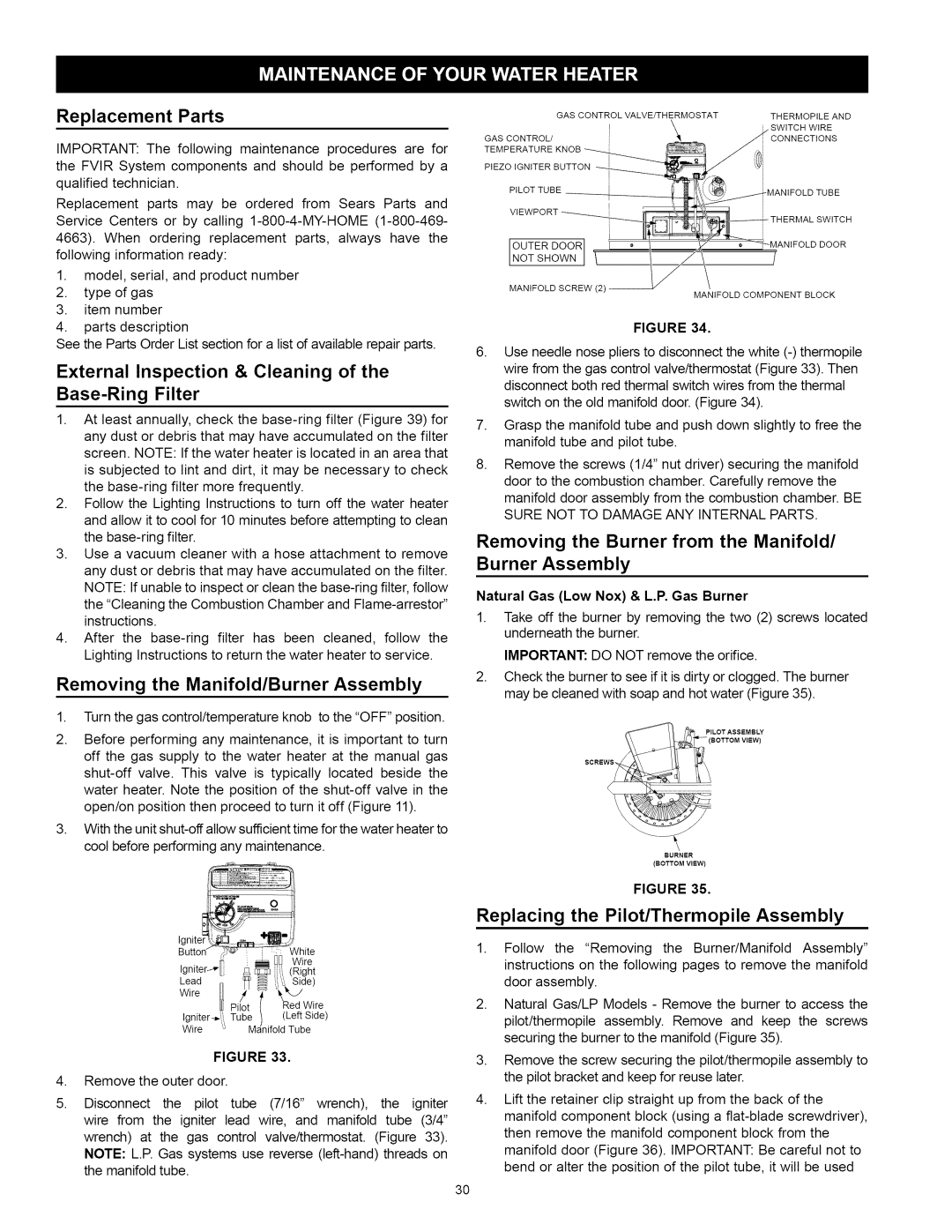
Replacement Parts

IMPORTANT: The following maintenance procedures are for the FVIR System components and should be performed by a qualified technician.

Replacement parts may be ordered from Sears Parts and Service Centers or by calling 1-800-4-MY-HOME (1-800-469- 4663). When ordering replacement parts, always have the following information ready:

1.model, serial, and product number

2.type of gas

3.item number

4.parts description

See the Parts Order List section for a list of available repair parts.

External Inspection & Cleaning of the

Base-Ring Filter

1.At least annually, check the base-ring filter (Figure 39) for

any dust or debris that may have accumulated on the filter screen. NOTE: If the water heater is located in an area that

is subjected to tint and dirt, it may be necessary to check the base-ring filter more frequently.

2.Follow the Lighting Instructions to turn off the water heater and allow it to coot for 10 minutes before attempting to clean the base-ring filter.

3.Use a vacuum cleaner with a hose attachment to remove any dust or debris that may have accumulated on the filter. NOTE: If unable to inspect or clean the base-ring filter, follow

the "Cleaning the Combustion Chamber and Flame-arrestor" instructions.

4.After the base-ring filter has been cleaned, follow the Lighting Instructions to return the water heater to service.

Removing the Manifold/Burner Assembly

1.Turn the gas control/temperature knob to the "OFF" position.

2.Before performing any maintenance, it is important to turn off the gas supply to the water heater at the manual gas shut-off valve. This valve is typically located beside the water heater. Note the position of the shut-off valve in the open/on position then proceed to turn it off (Figure 11).

3.With the unit shut-off allow sufficient time for the water heater to cool before performing any maintenance.

Ignite__S

Butte


irtee

Ignlter_"

i_

q


[_


"

_@i,

I, (Rght

Lead

n

%

_

,i'_

Side)

Wire

U

/4

_

_._J


[]J Pilot

/

Red

Wire

Igniter_,..t..

Tube

]

(Left

Side)

Wire

....

M_eifold

Tube

FIGURE 33.

4, Remove the outer door.

5.Disconnect the pilot tube (7/16" wrench), the igniter wire from the igniter lead wire, and manifold tube (3/4" wrench) at the gas control valve/thermostat. (Figure 33). NOTE: L.R Gas systems use reverse (left-hand) threads on the manifold tube.


GAS CONTROL

VALVE/THERMOSTAT

THERMOPILE

AND

GAS CONTROL/


CONNECTIONS

TEMPERATURE


PIEZOIGNITER

BUTTON


PILOT

TUBE


-MANIFOLD

TUBE

VIEWPORT


-THERMALSWITCH

OUTER DOOR]

NOT SHOWN J

MANIFOLD SCREW (2) --

MANIFOLD COMPONENT BLOCK

FIGURE 34.

6.Use needle nose pliers to disconnect the white (-) thermopile wire from the gas control valve/thermostat (Figure 33). Then disconnect both red thermal switch wires from the thermal switch on the old manifold door. (Figure 34).

7.Grasp the manifold tube and push down slightly to free the manifold tube and pilot tube.

8.Remove the screws (1/4" nut driver) securing the manifold door to the combustion chamber. Carefully remove the manifold door assembly from the combustion chamber. BE SURE NOT TO DAMAGE ANY INTERNAL PARTS.

Removing the Burner from the Manifold/

Burner Assembly

Natural Gas (Low Nox) & L.P. Gas Burner

1.Take off the burner by removing the two (2) screws located underneath the burner.

IMPORTANT: DO NOT remove the orifice.

2.Check the burner to see if it is dirty or clogged. The burner may be cleaned with soap and hot water (Figure 35).

(BOTTOM VIEW)

SCREW_

BURNER

(BOTTOM VIEW)

FIGURE 35.

Replacing the Pilot/Thermopile Assembly

1.Follow the "Removing the Burner/Manifold Assembly" instructions on the following pages to remove the manifold door assembly.

2.Natural Gas/LP Models - Remove the burner to access the pitot/thermopite assembly. Remove and keep the screws securing the burner to the manifold (Figure 35).

3.Remove the screw securing the pilot/thermopile assembly to the pilot bracket and keep for reuse later.

4.Lift the retainer clip straight up from the back of the manifold component block (using a flat-blade screwdriver), then remove the manifold component block from the manifold door (Figure 36). IMPORTANT: Be careful not to bend or alter the position of the pilot tube, it will be used

3O

Page 30
Image 30
Kenmore 153.33115, 153.33114 manual Replacement Parts, External Inspection & Cleaning Base-Ring Filter

153.33114, 153.33115 specifications

The Kenmore 153.33115 and 153.33114 are high-efficiency dehumidifiers designed to effectively manage moisture levels in residential spaces, providing comfort and safeguarding homes against the damaging effects of excess humidity. Both models embody Kenmore's commitment to quality, innovative technologies, and user-friendly features, making them ideal choices for maintaining optimal indoor air quality.

One of the standout features of the Kenmore 153.33115 and 153.33114 is their powerful dehumidification capability. With the capacity to remove up to 70 pints of moisture per day, these dehumidifiers efficiently tackle dampness in areas of up to 1,500 square feet. This makes them suitable for various spaces, including basements, laundry rooms, and even larger living areas, ensuring a healthy environment free from mold and mildew growth.

The models are equipped with an adjustable humidistat, which allows users to set their desired humidity levels easily. This feature not only enhances user control but also ensures energy efficiency by allowing the machines to operate only when necessary. Alongside energy efficiency, these dehumidifiers are designed to comply with Department of Energy guidelines, making them an eco-friendly choice.

Both models also feature a continuous drainage option, enabling hassle-free operation without the need for constant manual emptying of the water tank. When the water tank reaches capacity, an automatic shut-off function prevents overflow, ensuring peace of mind for users.

In terms of convenience, the Kenmore 153.33115 and 153.33114 have a user-friendly digital control panel with an easy-to-read LED display. This intuitive interface makes it simple to adjust settings, check humidity levels, and monitor overall performance. Additionally, the inclusion of wheels and a lightweight design enhances portability, allowing users to move the dehumidifiers where they are needed most.

Another notable aspect is the enhanced air filtration system. These dehumidifiers come with a removable, washable filter that effectively captures dust, allergens, and other airborne particles, contributing to better indoor air quality.

In conclusion, the Kenmore 153.33115 and 153.33114 are exemplary dehumidifiers that combine efficient moisture removal, user-friendly features, and eco-conscious designs. With their robust performance, effective humidity control, and added convenience features, these models stand out as reliable solutions for maintaining a comfortable and healthy indoor environment.