Installation Instructions (cont'd)
Temperature-Pressure Relief Valve
_,WARNING
At the time of manufacture this water heater was provided with a combination
by a nationally recognized testing laboratory that maintains periodic inspection of production of listed equipment or mate- rials, as meeting the requirements for Relief Valves and
Automatic Gas Shutoff Devicesfor Hot Water Supply Systems, and the latest edition of ANSI Z21.22 and the code require- ments of ASME. If replaced, the valve must meet the require- ments of local codes,but not less than a combination tempera- ture and pressure relief valve certified as meeting the require- ments for Relief Valves and Automatic Gas Shutoff Devicesfor Hot Water Supply Systems, ANSI Z21.22 by a nationally recog- nized testing laboratory that maintains periodic inspection of production of listed equipment or materials.
The valve must be marked with a maximum set pressure not to exceed the marked hydrostatic working pressure of the water heater (150 Ibs./sq.in.) and a discharge capacity not less than the water heater input rate as shown on the model rating plate. (Electric heaters - watts divided by 1000 x 3415 equal BTU/Hr. rate.)
Your local jurisdictional authority, while mandating the use of a
Compliance with such local requirements must be satisfied by the installer or end user of the water heater with a locally pre- scribed
nated opening in the water heater in place of the factory fur- nished valve.
For safe operation of the water heater, the relief valve must not be removed from it'sdesignated opening or plugged.
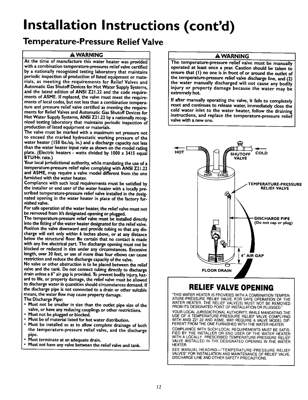
The temperature.pressure relief valve must be installeddirectly into the fitting of the water heater designatedfor the relief valve. Position the valve downward and provide tubing so that any dis- i
charge will exit only within 6 inches above, or at any distance below the structural floor Be certain that no contact is made
with any live electrical part. The dischargeopening must not be _locked or reduced in size under any circumstances. Excessive length, over 30 feet, or use of more than four elbows can cause restriction and reduce the dischargecapacity of the valve.
No valve or other obstruction is to be placed between the relief valve and the tank. Do not connect tubing directly to discharge drain unlessa 6" air gap is provided. To prevent bodilyinjury, haz. ard to life, or property damage, the relief valve must be allowed to dischargewater in quantities shouldcircumstancesdemand. If the discharge pipe is not connected to a drain or other suitable i means, the water flow may causeproperty damage.
The Discharge Pipe:
•Must not be smaller in size than the outlet pipe size of the valve, or have any reducing couplingsor other restrictions.
Must not be plugged or blocked.
Must be of material listed for hot water distribution.
Must be installed so as to allow complete drainage of both the
Must terminate at an adequate drain.
Must not haveany valve between the relief valve and tank.
AWARNING
The
If after manually operating the valve, it fails to completely
reset and continues to release water, immediately close the
cold water inlet to the water heater, follow the draining
nstructions, and replace the
HOTCOLD
VALVE
RELIEF VALVE
[] | (Do not cap or plug) |
6" AIR GAP
FLOOR ORAN I
RELIEF VALVE OPENING
"THIS WATER HEATER IS PROVIDED WITH A COMBINATION TEMPER-
WATER HEATER, THE RELIEF VALVE(S) MUST NOT BE REMOVED FROM ITS DESIGNATED POINT OF INSTALLATION OR PLUGGED."
YOUR LOCAL 3UR_SDICT_ONALAUTHORITY,WH_LE MANDATING THE USE OF A
WITH ANSI Z21.22 AND ASME, MAY REQUIRE A VALVE MODEL DIF- FERENT FROM THE ONE FURNISHED WITH THE WATER HEATER.
COMPLIANCE WITH SUCH LOCAL REQUIREMENTS MUST BE SATIS-
FIED BY THE INSTALLER OR END USER OF THE WATER HEATER WITH A LOCALLY PRESCRIBED
VALVE INSTALLED IN THE DESIGNATED OPENING IN THE WATER HEATER.
SEE MANUAL
VALVES" FOR INSTALLATION AND MAINTENANCE OF REUEF VALVE, DISCHARGE LINE AND OTHER SAFETY PRECAUTIONS.
12