Installation Instructions (cont'd)
• LESSTHAN
120"
POWER VENT J
TERMINAL 12"rain.
FORCED AIR
INLET
Figure 3a I
VENT TERMINAL
f |
|
|
|
| 18" TO WALL OR OTHER |
J_lS" | MIN. _ | OBSTRUCTIONS THAT |
|
| MAY INTERFERE WFTH |
|
| VENTING. |
|
| VENT TERMINAL |
|
| CORNER OF BUILDING |
Figure 3b I
POWER VENTTERMINAL _js |
_ |
| , | / DIRECT VENT, POWER VENT | |
| _ | _/ |
| OR POWER D,RECT VENT |
| 24" |
| APPDANCEINLETAND/OR |
Figure 3c]
MUST MAINTAIN
ADEQUATE SERVICE
|
|
|
| AVAILABLE FOR VENT |
Figure 4 | ] | .... | " | PIPEINSTALLATION. |
|
|
|
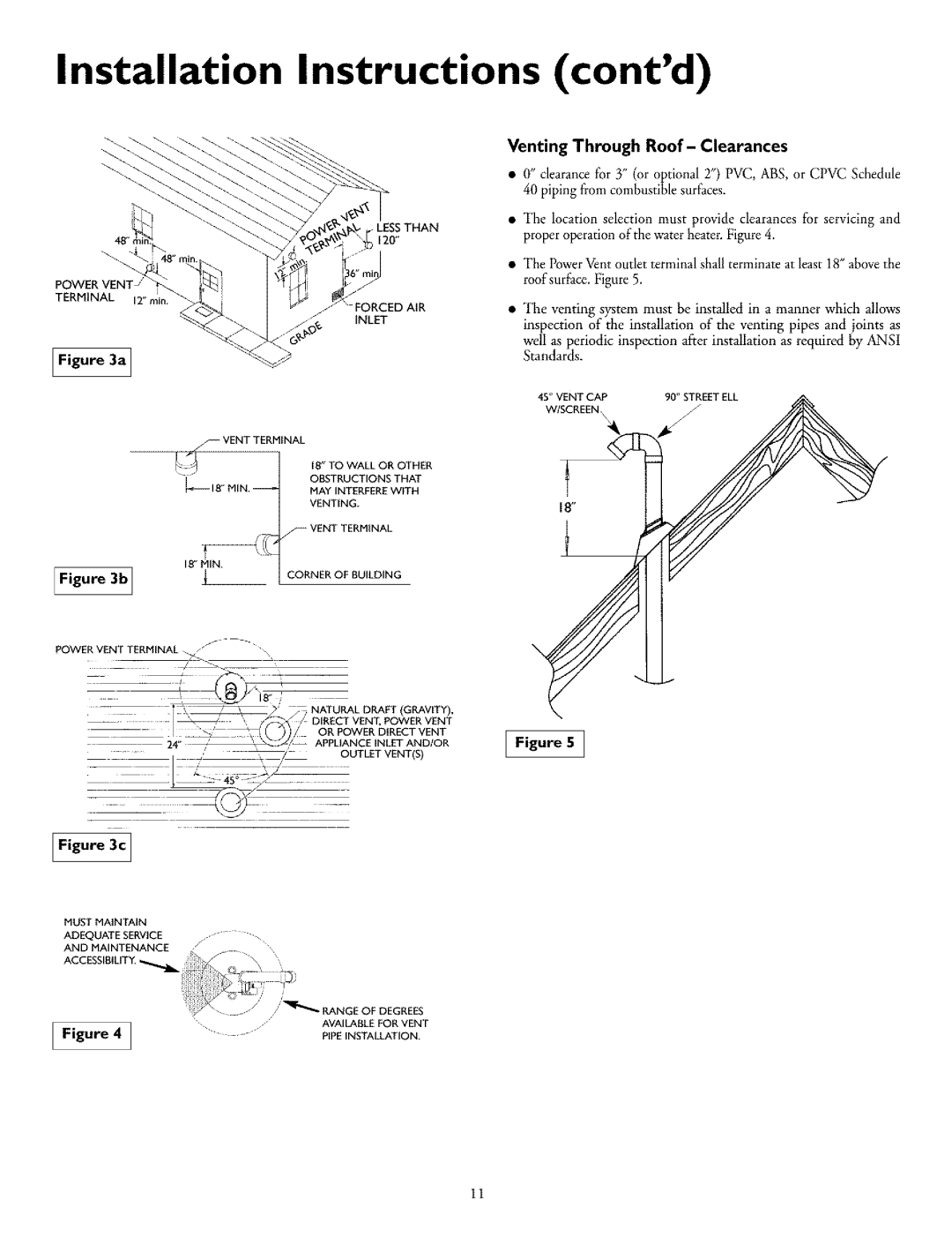
Venting Through Roof- Clearances
•0' clearance for Y' (or opt'onal 2") PVC, ABS, or CPVC Schedule 40 piping from combustiblesurfaces.
•"The location selection must provide clearances for servicing and proper operation of the water heater• Figure 4.
•"The Power Vent outlet terminal shall terminate at least 18" above the roof surface. Figure 5.
•The venting system must be installed in a manner which allows inspection of the installation of the venting pipes and joints as
well as periodic inspection aiier installation as required by ANSI Standards.
45° VENT CAP | 90° STREET ELL |
N
Figure 5 ]
11