Kenmore 153.33288, 153.33296, 153.332870HA Reliefvalveopening, Temperature-PressureRelief Valve

Models: 153.332960HA 153.33298 153.332890HA 153.332990HA 153.33296 153.33288 153.332861 153.332870HA

1 44
Download 44 pages 39.07 Kb
Page 14
Image 14
Temperature-Pressure Relief Valve

Installation Instructions (cont'd)

Temperature-Pressure Relief Valve

AWARNING

At the time of manufacture this water heater was provided with a combinationtemperature-pressuresreliefvalvecerti- fied bya nationallyrecognized testinglaboratory that main- tains periodic inspectionof productionof listedequipment or materials, as meeting the requirements for ReliefValves and Automatic Gas ShutoffDevices for Hot Water Supply Systems,and the current edition of ANSI Z21.22, CSA 4.4 Standardsand the code requirements of ASME. If replaced, the valve must meet the requirements of local codes, but not lessthan a combinationtemperature and pressurerelief valvecertified as meeting the requirements for ReliefValves and Automatic Gas ShutoffDevices for Hot Water Supply Systems,ANSI Z21.22 • CSA 4.4 Standardsby a nationally recognized testing laboratory that maintains periodic inspectionof productionof listedequipmentor materials. The valve must be marked with a maximum set pressure not to exceed the marked hydrostaticworking pressureof the water heater (150 Ibs./sq.in.) and a dischargecapacity not lessthan the water heater input rate as shownon the model rating plate. (Electric heaters- watts dividedby 1000 x 3412 equalBTU/Hr. rate.)

Your localjurisdictionalauthority, while mandatingthe use of a temperature-pressurereliefvalvecomplyingwith ANSI

Z21.22 CSA 4.4 Standardsand ASME, may require a valve model different from the one furnished with the water

heater.

Compliance with such localrequirements must be satisfied by the installeror end user of the water heater with a locally _rescribedtemperature-pressurereliefvalve installedin the designatedopeningin the water heater in placeof the facto- ry furnishedvalve.

For safeoperation of the water heater, the relief valvemust not beremoved from it'sdesignatedopeningor plugged. The temperature-pressure relief valve must be installed directly into the fitting of the water heater designatedfor the relief valve. Positionthe valve downward and provide tubing so that any dischargewill exit only within 6 inches above,or at any distancebelowthe structuralfloor. Be cer- tain that no contact is made with any live electrical part. The dischargeopening must not be blockedor reduced in

size under anycircumstancesExcessivelength,over. 30 feet, or use of more than four elbowscan causerestriction and

reduce the dischargecapacityof the valve.

No valve or other obstructionis to be placedbetween the relief valveand the tank. Do not connecttubing directly to dischargedrain unlessa 6" air gap is provided.To prevent bodily injury, hazard to life, or property damage, the relief valve must be allowed to discharge water in quantities shouldcircumstancesdemand. If the dischargepipe is not connected to a drain or other suitable means, the water flow may causeproperty damage.

The DischargePipe:

Must not be smallerin sizethan the outlet pipesize of the valve,or haveanyreducing couplingsor other restrictions.

Must not be pluggedor blocked.

Must be of material listedfor hot water distribution.

Must be installedsoas to allowcomplete drainageof both the temperature-pressurereliefvalve, and the discharge pipe.

Must terminate at anadequatedrain.

Must not haveanyvalvebetweenthe relief valveand tank.

_'LWARNING

The temperature-pressure relief valve must be manually operated at least once a year. Caution shouldbe taken to ensurethat (I) no one isin front of or around the outlet of the temperature-pressure relief valve dischargeline, and

(2)the water manually dischargedwill not causeany bodi- ly injury or property damage because the water may be extremely hot.

If after manually operating the valve, it fails to completely reset and continues to release water, immediately close the cold water inlet to the water heater,follow the drain- ing instructions, and replace the
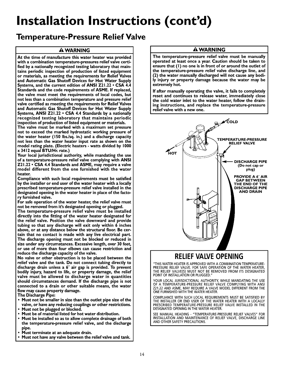
 temperature-prossuro relief valvewith a new one.

TEMPERATURE-PRESSURE

R_LIEF VALVE

DISCHARGE PIPE

I I_ (Do not cap or

I1\

II \ PROVIDEA6"AIR

I I \ GAP BETWEEN

I I t THE END OF THE

I I DISCHARGE PIPE

__

AND DRAIN

RELIEFVALVEOPENING

"THISWATERHEATERISAPPROVEDWITH A COMBINATIONTEMPERATURE-

PRESSURERELIEFVALVE. FOR SAFEOPERATIONOF THE WATER HEATER, THE RELIEFVALVE(S) MUST NOT BE REMOVED FROM ITS DESIGNATED

POINTOF INSTALLATIONORPLUGGED."

YOUR LOCALJURISDICTIONALAUTHORITY,WHILE MANDATING THE USE OF A TEMPERATURE-PRESSURERELIEFVALVE COMPLYING WITH ANSI

Z21.22 AND ASME, MAY REQUIREA VALVEMODEL DIFFERENTFROM THE ONEFURNISHEDWITH THE WATERHEATER.

COMPLIANCEWITH SUCH LOCALREQUIREMENTSMUST BE SATISFIEDBY THE INSTALLEROR END USEROF THE WATERHEATERWITH A LOCALLY

PRESCRIBEDTEMPERATURE-PRESSURERELIEFVALVE INSTALLED IN THE DESIGNATEDOPENINGIN THEWATERHEATER.

SEE MANUAL HEADING - "TEMPERATURE-PRESSURERELIEFVALVES" FOR

INSTALLATION AND MAINTENANCE OF RELIEFVALVE, DISCHARGELINE AND OTHERSAFETYPRECAUTIONS.

14

Page 14
Image 14
Kenmore 153.33288, 153.33296 Reliefvalveopening, Temperature-PressureRelief Valve, Installation Instructions contd