Installation Instructions (cont'd)
Venting
_WARNING
To insure proper venting of this
with this water heater will adversely affect the oper- ation of the water heater.
The combustion alld ventilation air flow must not be obstructed.
AWARNING
The power vent water heater requires its own (sepa- rate) venting system. It cannot be connected to an ex-
isting vent pipe or chimney. It must be terminated to the outdoors. Failure to properly install the venting sys-
tem can result in asphyxiation, a fire or explosion and
can cause DEATH, SERIOUS BODILY INJURY, OR PROPERTY DAMAGE.
Obstructed or deteriorated vent systems may
WARN I NGpre-
sent a serious health risk or asphyxiation.
The vent pipe from the water heater must
_, WARN I NGslope upward % inch per five linear feet.
&WARNING
Chemical vapor corrosion of the flue and vent sys- tem may occur if air for combustion contains certain chemical vapors. Spray can propellants, cleaning sol-
vents, refrigerator and air conditioner refrigerants, swimming pool chemicals, calcium and sodium chlo- ride, waxes, bleach, and process chemicals are typi- cal compounds which are potentially corrosive.
\
STRAPPING
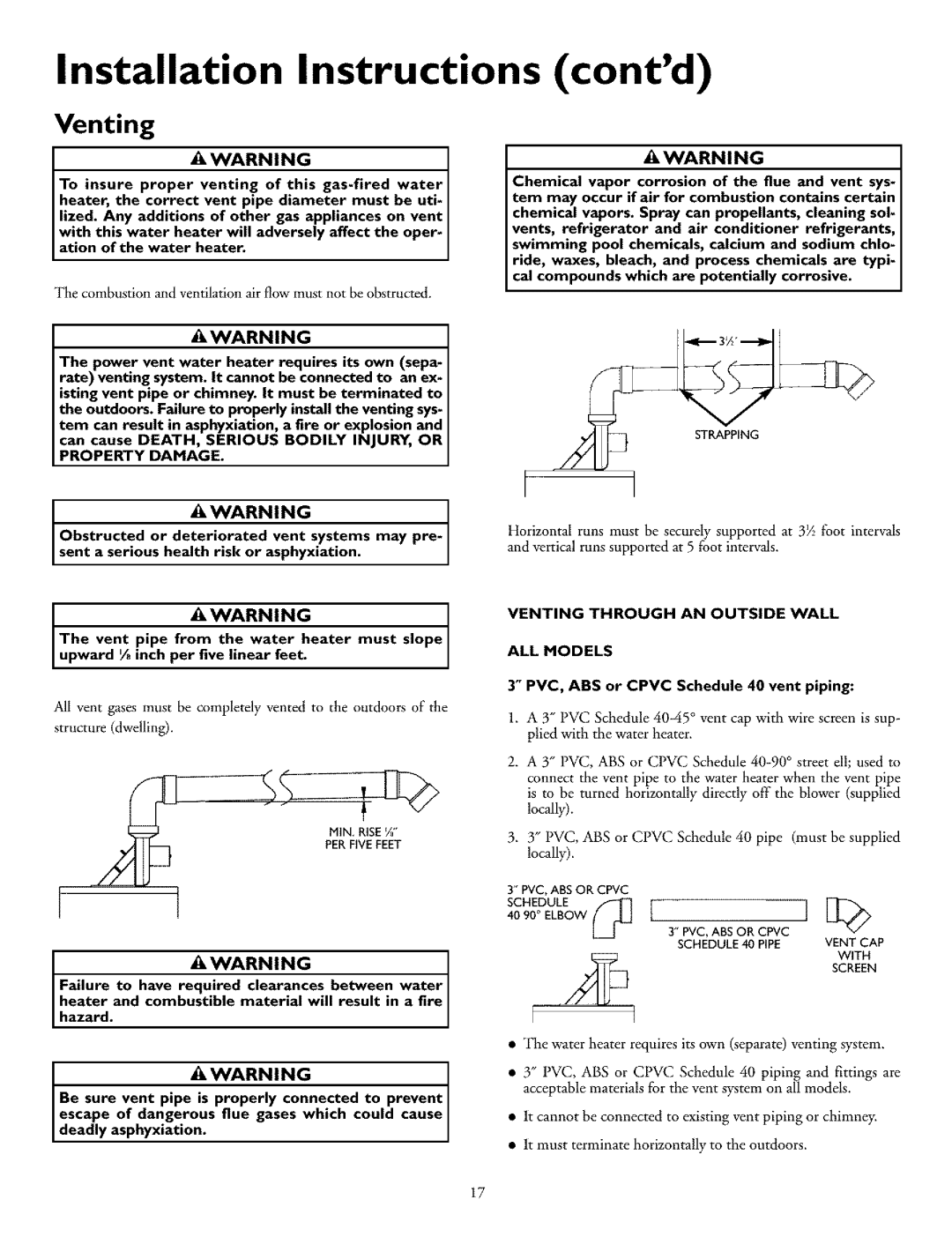
Horizontal runs must be securely supported at 3V2foot intervals and vertical runs supported at 5 foot intervals.
VENTING THROUGH AN OUTSIDE WALL
ALL MODELS
3" PVC, ABS or CPVC Schedule 40 vent piping:
MI vent gases must be completely vented to the outdoors of the
structure (dwelling).
MIN. RISE½'
PERFIVEFEET
AWARNINGI
Failure to have required clearances between water I
heater and combustible material will result in a fire hazard.
&WARNINGI
Be sure vent pipe is properly connected to prevent I
escape of dangerous flue gases which could cause
dead y asphyx at on.
1.A Y" PVC Schedule
2.A 3 I VC, ABS or CPVC Schedule
connect the vent pipe to the water heater when the vent pipe is to be turned horizontally directly off" the blower (supplied
locally).
3.3 _tVC, ABS or CPVC Schedule 40 pipe (must be supplied locally).
3" PVC,ABS OR CPVC
SCHEDULE
4ogOOELOOWt
3" PVC,ABSOR CPVC
SCHEDULE40 PiPE VENTCAP
SCREEN
WITH
•The water heater requires its own (separate) venting system.
•3 I VC, ABS or CPVC Schedule 40 piping and fittings are acceptable materials for the vent system on all models.
•It cannot be connected to existing vent piping or chimney.
•It must terminate horizontally to the outdoors.
17