Installation Instructions (cont'd)
Temperature-Pressure Relief Valve
_-- AWARNING
At the time of manufacturethis water heater was provided
with a
periodicinspectionofproductionof listedequi.mentp, or mate- rials, as meeting the requirements for Rehef Valves and
Automatic GasShutoffDevicesfor Hot Water SupplySystems, and the latest edition of ANSI Z21.22 and the code require.
ments of ASME. If replaced, the valvemust meet the require. ments of local codes,but not lessthan a combinationtempera-
ture and pressure reliefvalvecertified as meetingthe require- mentsfor ReliefValvesand Automatic GasShutoffDevicesfor
Hot Water SupplySystems,ANSI Z21.22 bya nationally recog- nized testinglaboratory that maintains periodicinspectionof productionof listedequipmentor materials.
he valve must be marked with a maximum set pressurenot to exceed the marked hydrostaticworking pressure of the water heater (150 Ibs./sq.in,) and a dischargecapacitynot less than the water heater input rate asshownon the modelrating plate. (Electric heaters- watts dividedby 1000 x 3415 equal
BTU/Hr. rate.)_.
Yourlocaljurisdictionalauthority,whilemandatingthe useof a
Compliancewith suchlocalrequirements mustbe satisfiedby the installeror end userof the water heater with a locallypre-
Forsafeoperationofthe water heater,the relief valvemustnot be removed from it'sdesignatedopeningor plugged,
The
chargewill exit only within 6 inchesabove,or at any distance belowthe structuralfloor. Be certainthat no contactis made
with any liveelectricalpart.The dischargeopeningmustnot be blockedor reduced in size underany circumstances.Excessive
length, over 30 feet,or useof more than four elbowscancause restriction andreducethe dischargecapacityofthe valve.
No valveor other obstructionisto beplacedbetweenthe relief valveand the tank. Do not connecttubingdirectlyto discharge drain unlessa 6" air gapisprovidedTopreventbodilyinjury,haz.- ard to life,or propertydamage,the relief valvemustbeallowed to dischargewater in quantitiesshouldcircumstancesdemand.If the dischargepipe isnot connectedto a drain or other suitable means,the waterflowmay causepropertydamage.
The DischargePipe:
Must not be smallerin size than the outlet pipe size of the I " valve,or haveany reducingcouplingsor other restrictions.
Must not be pluggedor blocked.
Must beof materiallistedfor hot water distribution.
Must be installedso as to allowcomplete drainageof both the
Mustterminateat anadequatedrain.
Must not haveanyvalvebetweenthe relief valveand tank,
_,WARNING
The temperature.pressure relief valve must be manually operated at least once a year. Caution should be taken to ensurethat (I) no one is in front of or aroundthe outlet of the
If after manually operating the valve, it fails to completely reset and continuesto releasewater, immediately closethe
cold water inlet to the water heater, follow the draining instructions,and replace the
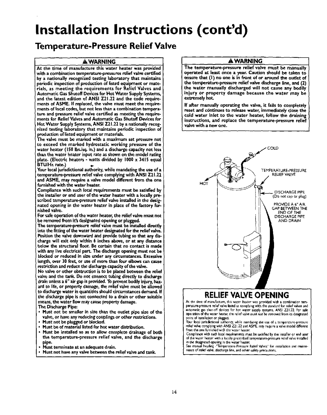
| ||
HOT | / | RELIEFVALVE |
• DISCHARGE PIPE {D_ r_ot cap or plus)
PROVIDE A 6" AIR
GAP BETWEEN THE
END OF THE
DISCHARGE PiPE
AND DRAIN
RELIEFVALVE OPENING
At the tir_e of manufacture, this water heater was provided with a combination tem-
operationofthe waterheater,the relief valvemustnot be removedfromitsdesignated
point of installationor plugged.
Your local jurisdictional authority, while mandating the use of a
from the onefurnishedwiththe waterheater,
Compliancewithsuchlocalrequirementsmustbe satisfiedbythe installeror enduser
of the water heater with a
See manual
14