Digital connections
Setting up the system
1 1
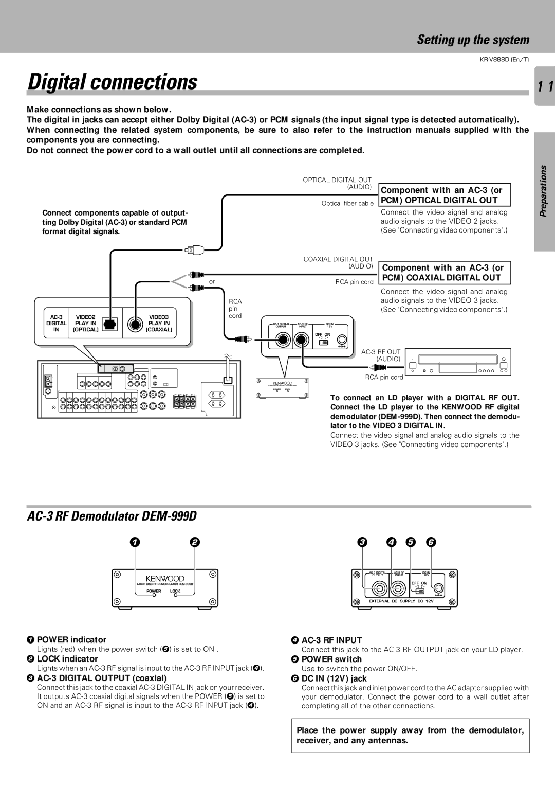
Make connections as shown below.
The digital in jacks can accept either Dolby Digital
Do not connect the power cord to a wall outlet until all connections are completed.
OPTICAL DIGITAL OUT (AUDIO)
Optical fiber cable
Connect components capable of output- ting Dolby Digital
Component with an
PCM) OPTICAL DIGITAL OUT
Connect the video signal and analog audio signals to the VIDEO 2 jacks. (See "Connecting video components".)
Preparations
IN (OPTICAL)
COAXIAL DIGITAL OUT (AUDIO)
or |
|
| RCA pin cord |
| RCA |
|
|
| pin |
|
|
VIDEO3 | cord |
|
|
PLAY IN | DC IN | ||
(COAXIAL) | OUTPUT | INPUT | 12V |
|
| OFF ON | |
|
|
| |
|
|
| @ # |
Component with an
PCM) COAXIAL DIGITAL OUT
Connect the video signal and analog audio signals to the VIDEO 3 jacks. (See "Connecting video components".)
RCA pin cord
LASER DISC RF DEMODULATOR
POWER LOCK
To connect an LD player with a DIGITAL RF OUT. Connect the LD player to the KENWOOD RF digital demodulator
Connect the video signal and analog audio signals to the VIDEO 3 jacks. (See "Connecting video components".)
AC-3 RF Demodulator DEM-999D
12
LASER DISC RF DEMODULATOR
POWER LOCK
1POWER indicator
Lights (red) when the power switch (5) is set to ON .
2LOCK indicator
Lights when an
3AC-3 DIGITAL OUTPUT (coaxial)
Connect this jack to the coaxial
34 5 6
DC IN | ||
OUTPUT | INPUT | 12V |
OFF ON @ #
EXTERNAL DC SUPPLY DC 12V
4AC-3 RF INPUT
Connect this jack to the
5POWER switch
Use to switch the power ON/OFF.
6DC IN (12V) jack
Connect this jack and inlet power cord to the AC adaptor supplied with your demodulator. Connect the power cord to a wall outlet after completing all of the other connections.
Place the power supply away from the demodulator, receiver, and any antennas.
