TK-940 specifications
The Kenwood TK-940 is a highly regarded mobile two-way radio that has earned a reputation for its ruggedness, reliability, and excellent communication capabilities. Designed for professionals in various sectors such as public safety, transportation, and construction, the TK-940 incorporates advanced technologies to meet the demanding needs of users in the field.One of the standout features of the TK-940 is its robust design, which complies with military specifications for durability. Its construction allows it to withstand harsh environmental conditions, making it suitable for outdoor and challenging work environments. The radio is also equipped with a water-resistant casing, ensuring that it can function reliably even in wet conditions.
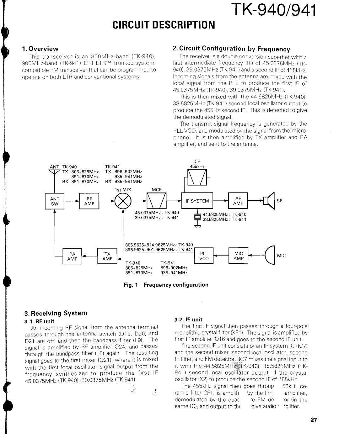
The TK-940 operates in the VHF frequency range, providing wide coverage and strong signal penetration. With a power output of up to 110 watts, users can achieve long-range communication, essential for coordinating activities over large areas. The radio supports both analog and digital modes, allowing seamless integration into various communication systems while maintaining high audio clarity.
Another significant feature of the TK-940 is its enhanced audio quality. The radio is equipped with Kenwood's advanced noise cancellation technology, which minimizes background noise and ensures clear voice communication even in noisy environments. The audio output is powerful and adjustable, catering to individual user preferences.
Moreover, the TK-940 supports a variety of signaling options, includingDTMF, MDC-1200, and 2-Tone/5-Tone signaling, facilitating efficient communication. These signaling features enhance interoperability with other communication devices and systems, allowing users to communicate seamlessly with teams or dispatch centers.
Kenwood has also incorporated user-friendly functionalities into the TK-940. It boasts an intuitive user interface with programmable buttons, enabling quick access to essential features. The large, backlit display provides clear visibility and is easy to read in various lighting conditions.
The TK-940 is designed with safety in mind, featuring emergency alerts and lone worker protection, ensuring users can communicate their status in critical situations. Overall, the Kenwood TK-940 is a powerful and versatile mobile radio that combines durability, advanced technology, and user-friendly features, making it an ideal choice for professionals who require reliable communication in the field.

