SEMICONDUCTOR DATA

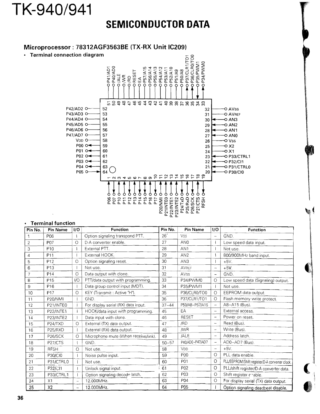
Microprocessor : 78312AGF3563BE (TX-RX Unit IC209)

Terminal connection diagram

- 0

z ~ % % % S % s ~ 7 s 3 a % L % R ~ %

P42lAD2

52


32


P43lAD3

53


31


P44lAD4

5 4


30


P45lAD5

55


29


P46lAD6

56


28


P47lAD7

57


27


Vuo

58


26

vss

PO0

59


25

4X2

PO1

60


24

4X I

PO2

6 1


23

M P33lCTRLl

PO3

62


22

P32ICll

Po4

63

n

2

i

V


-PBIICTRLO


-P3OlCIO

Terminal function

Pin No.

Pin Name

I10

Function


Pin No.

Pin Name

11/0


Function


1

PO6

I

Opt~onsignaling transpond PTT.


26'

1 Vss

1

-

-

GND.


p--


27


/


I

7

PO7

0

D-A converter enable.


AN0

I


Low m e e d data innut.

--


I

External PTT


-


28

AN1


I


-


3

P I0


Not use


4

P I 1

I

External HOOK


29

AN2 - I


800/900MHz band input


5

P12

0 Olnt~ons~qnal~nq- - reset


30

AN3

0

6

P13

I

Not use.


3 1-TAVREF --+5V.


7

P I 4

0

Data output with clone.


32

AVss


-


GND.


8

P I 5

110

PTTIdata output with programming.


33

P34lPWMO


O


L o w speed data (Signaling) output.


9

P16

I Data group control input (MDT).


34

P35lPWMI


I


Not use.


10

P I7

0

KEY (Transmit : Active "H").


35

P36/CLROR00


0


E'EPROMdata output.


--


-


-


11

P20INMI

7GND.


36

P37lCLRlR01


O


Flash memory write protect.


12

P21/1NTEO

I

For display serial (RX) data input.


37-44

P501A8-P57lA15


-


A8-A15--(Bus).


13

P22/1NTEl

I


--


45

-EA


-


External -access.


HOOKfdata input with programming.


-


Power on reset.


14

P23/INTE2

I

Data inputwith clone.

--


46

RESET


pp


15

P24nXD

0

External (TX) data output.


47

/RD


-


Read (Bus).


-


----


16

P25/RXD

I

External (RX) data output.


48

/WRp


W--r ~ t e(Bus).


--


-


17

P26/SCK- 0

M~crophonemute (When receive/iink).


49

/ALE-


Address latch-.


-


P40lADO.- -P471AD7


-


ADO-AD7 (BUS).


18

P27lCTS

-- I

GND.


50-57


19

RFSH

Not use.


VDD-


-


+5V.


0


58


20

P3O/CIO

I

Noise pulse input.


59

PO0


0


PLL data enable.


~-


PO 1


0


PLUEEPROMlShift register/^-^converterclock.


21

P31/CTRLO

I

Not use.

-

60


22

~ 3 8 , 2 1 1

I

Unlock signal input.

61

PO2


0


PLLIshift registerID-A converter data.


1


23

P33/CTRLI

I

Option signaling decode latch.


62

--PO3


0


Shift register ~ ~ a b l e .


0 -

24

XI

-

12.000MHz.


63

PO4


0


For display serial (TX) data output.

25

X2


PO5


Page 36
Image 36
Kenwood TK-940 service manual Microprocessor 78312AGF3563BE TX-RX Unit IC209

TK-940 specifications

The Kenwood TK-940 is a highly regarded mobile two-way radio that has earned a reputation for its ruggedness, reliability, and excellent communication capabilities. Designed for professionals in various sectors such as public safety, transportation, and construction, the TK-940 incorporates advanced technologies to meet the demanding needs of users in the field.

One of the standout features of the TK-940 is its robust design, which complies with military specifications for durability. Its construction allows it to withstand harsh environmental conditions, making it suitable for outdoor and challenging work environments. The radio is also equipped with a water-resistant casing, ensuring that it can function reliably even in wet conditions.

The TK-940 operates in the VHF frequency range, providing wide coverage and strong signal penetration. With a power output of up to 110 watts, users can achieve long-range communication, essential for coordinating activities over large areas. The radio supports both analog and digital modes, allowing seamless integration into various communication systems while maintaining high audio clarity.

Another significant feature of the TK-940 is its enhanced audio quality. The radio is equipped with Kenwood's advanced noise cancellation technology, which minimizes background noise and ensures clear voice communication even in noisy environments. The audio output is powerful and adjustable, catering to individual user preferences.

Moreover, the TK-940 supports a variety of signaling options, includingDTMF, MDC-1200, and 2-Tone/5-Tone signaling, facilitating efficient communication. These signaling features enhance interoperability with other communication devices and systems, allowing users to communicate seamlessly with teams or dispatch centers.

Kenwood has also incorporated user-friendly functionalities into the TK-940. It boasts an intuitive user interface with programmable buttons, enabling quick access to essential features. The large, backlit display provides clear visibility and is easy to read in various lighting conditions.

The TK-940 is designed with safety in mind, featuring emergency alerts and lone worker protection, ensuring users can communicate their status in critical situations. Overall, the Kenwood TK-940 is a powerful and versatile mobile radio that combines durability, advanced technology, and user-friendly features, making it an ideal choice for professionals who require reliable communication in the field.