9401941

EINSTALLATION

e vehicle and determine how and where

cable runs for protection against pinching or g wiring, and radio installation to prevent,over-

4-2. Antenna

The favored location for an antenna Is In the center of a large, flat conduct~vearea, usually at the roof ten- ter The trunk Ild IS preferred, bond the trunk and vehicle chassis using ground straps t o ensure the Ild 1s at chassis ground

4-3. Radio

The universal mount bracket allows the radio to be mounted in a variety of ways. Be sure the mounting surface is adequate to support the radio'sweight. Al- low sufficient space around the radio for air cooling. Position the radio close enough to the vehicle operator to permit easy access to the controls when driving.

4-4. DC Power and wiring

1Th~srad~omay be ~nstalledIn negatlve ground eec - tr~calsystems only Reverse polar~tywill cause the

cable fuse to blow Check the veh~cleground polar-

f~ t ybefore ~nstallat~on prevent wasted time and

I

1

effort

k

2 Connect the posltive power lead d~rectlyto the ve-

th~clebattery pos~tiveterm~nalConnect~ngthe Posi-

i tive lead to any other posltlve voltage source In the

I.t veh~cleIS not recommended

F

1 """""If DC power is to be controlled by the vehicle ign~tion switch, a switching relay should be used to switch the

/posltwe power lead The vehcle ignition switch then controls DC to the relay c o ~ l

1

I

1 3 Connect the ground lead d~rectly o the battery negatlve termlnal

4The cable prov~dedwlth the radlo IS s u f f ~ c ~ e nto handle the maximum radio current demand If the cable must be extended, be sure the addit~onalwire IS suff~c~entfor the current to be carr~edand length of the added lead

5.INSTALLATION PLANNING - CONTROL STATIONS 5-1. Antenna system

Control station. The antenna system seect~onde- pends on many factors and IS beyond the scope of this manual. Your KENWOOD dealer can help you select an antenna system that will best serve your particular needs.

5-2. Radio location

Select a convenlent location for your control stat~on rad~owhich is as close as practical to the antenna cable entry pornt Secondly, use your system'spower supply (whlch supplles the voltage and current requ~redfor your system) Make sure suff~c~entair can flow around the rad~oand power supply to allow adequate cool~ng

SERVICE

This radio is designed for easy servicing. Refer to the schematic diagrams, printed circuit board views, and alignment procedures contained in this manual.

Note

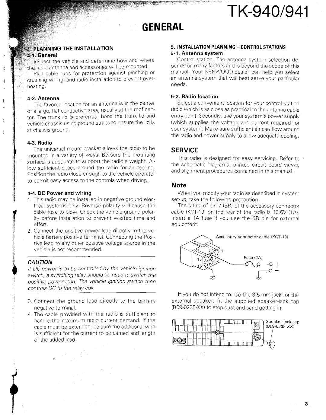
When you modify your radio as described in systern set-up, take the following precaution.

The rating of pin 7 (SB) of the accessory connector cable (KCT-19) on the rear of the radio is 13.6V ( I A ) . Insert a 1A fuse if you use the SB pin for external

equipment.

Accessory connector cable (KCT-19)

Fuse (IA)

If you do not intend to use the 3.5-mm jack for the external speaker, fit the supplied speaker-jack cap (B09-0235-XX) to stop dust and sand getting in.

Speaker-jack cap (B09-0235-XX)

Page 3
Image 3
Kenwood TK-940 DC Power and wiring, Installation Planning Control Stations 5-1. Antenna system, Radio location

TK-940 specifications

The Kenwood TK-940 is a highly regarded mobile two-way radio that has earned a reputation for its ruggedness, reliability, and excellent communication capabilities. Designed for professionals in various sectors such as public safety, transportation, and construction, the TK-940 incorporates advanced technologies to meet the demanding needs of users in the field.

One of the standout features of the TK-940 is its robust design, which complies with military specifications for durability. Its construction allows it to withstand harsh environmental conditions, making it suitable for outdoor and challenging work environments. The radio is also equipped with a water-resistant casing, ensuring that it can function reliably even in wet conditions.

The TK-940 operates in the VHF frequency range, providing wide coverage and strong signal penetration. With a power output of up to 110 watts, users can achieve long-range communication, essential for coordinating activities over large areas. The radio supports both analog and digital modes, allowing seamless integration into various communication systems while maintaining high audio clarity.

Another significant feature of the TK-940 is its enhanced audio quality. The radio is equipped with Kenwood's advanced noise cancellation technology, which minimizes background noise and ensures clear voice communication even in noisy environments. The audio output is powerful and adjustable, catering to individual user preferences.

Moreover, the TK-940 supports a variety of signaling options, includingDTMF, MDC-1200, and 2-Tone/5-Tone signaling, facilitating efficient communication. These signaling features enhance interoperability with other communication devices and systems, allowing users to communicate seamlessly with teams or dispatch centers.

Kenwood has also incorporated user-friendly functionalities into the TK-940. It boasts an intuitive user interface with programmable buttons, enabling quick access to essential features. The large, backlit display provides clear visibility and is easy to read in various lighting conditions.

The TK-940 is designed with safety in mind, featuring emergency alerts and lone worker protection, ensuring users can communicate their status in critical situations. Overall, the Kenwood TK-940 is a powerful and versatile mobile radio that combines durability, advanced technology, and user-friendly features, making it an ideal choice for professionals who require reliable communication in the field.