Contents
Controller DC-RET Digital Control
Models
TP-6516 4/09d
Engine Identification
Product Identification Information
Generator Set Identification Numbers
Controller Identification
Table of Contents
TP-6516 4/09
Battery
Safety Precautions and Instructions
Accidental Starting
Exhaust System
Engine Backfire/Flash Fire
Fuel System
Hazardous Voltage/ Moving Parts
Hazardous Noise
Heavy Equipment
Hot Parts
Introduction
Detail
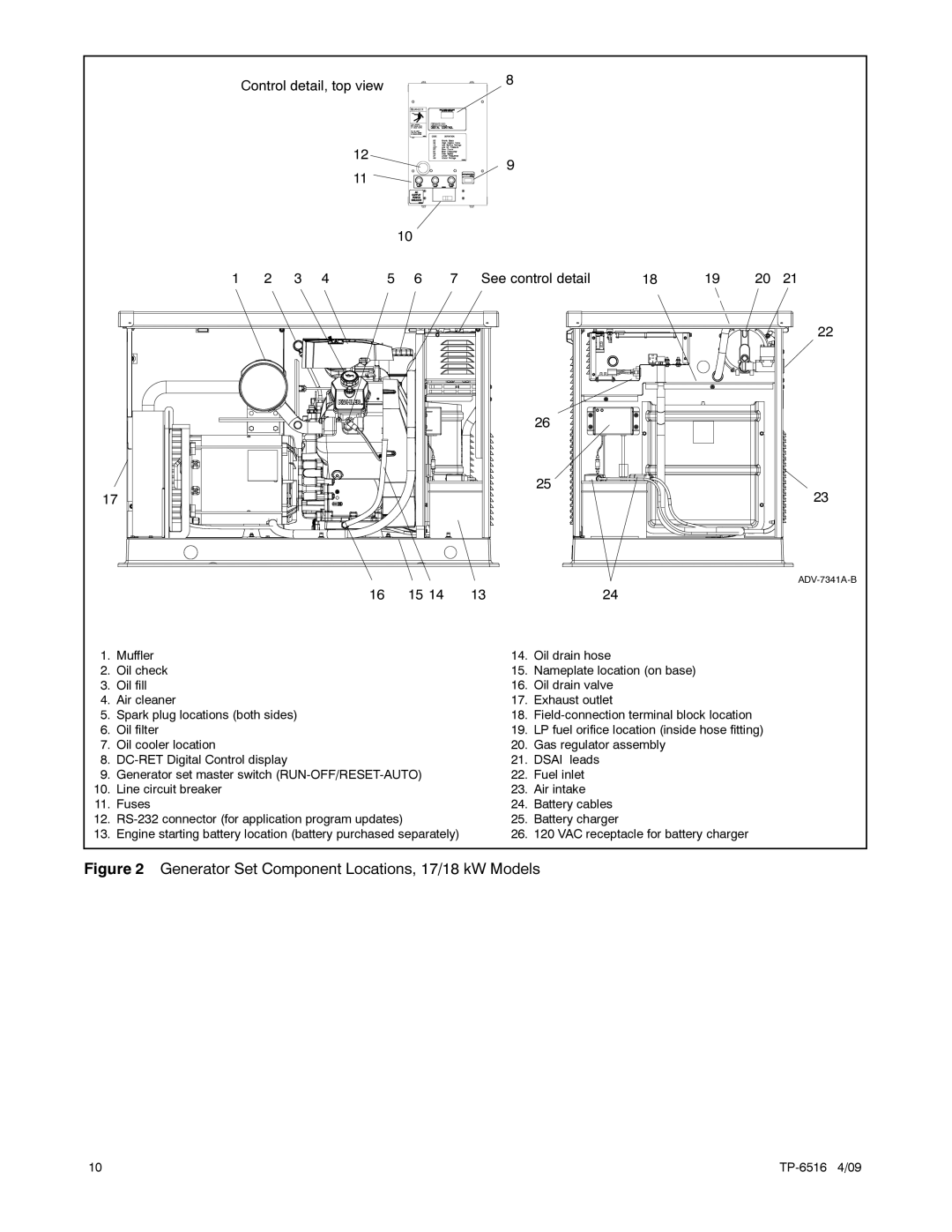
Generator Set Component Locations, 17/18 kW Models
Service Assistance
TP-6516 4/09
Lifting
Installation
General
Generator Set Inspection
See Section
Generator Set Clearances, 12 kW Models, ADV-7466, Sheet
Installation TP-6516 4/09
Generator Set Clearances, 17/18 kW Models, ADV-7341-B, Sheet
Exhaust Requirements
Power Supply
Air Requirements
Fuel Requirements
Fuel Supply
Fuel Pipe Size
Fuel Conversion
Fuel Conversion
17 Dsai Connection
Electrical Connections
AC Connections
Remote Start Connection
Battery Charger
Grounding
EZ-273000-J
Engine starting battery location
Carburetor Heater optional
24 Carburetor Heater, 17/18 kW
Prestart Installation Check
Startup Notification
Installation TP-6516 4/09
Wiring Diagrams
Wiring Diagrams and Schematics
Schematic Diagram, 12 kW Models, ADV-7351
Point-to-Point Wiring Diagram, 12 kW Models, GM52471
Schematic Diagram, Single Phase, 17/18 kW Models, ADV-7353
TP-6516 4/09 Wiring Diagrams
Wiring Diagrams TP-6516 4/09
Appendix a Abbreviations
Ansi
LCB
TP-6516 4/09
TP-6516 4/09
Page
2007, 2008, 2009 by Kohler Co. All rights reserved