Introduction
This manual provides installation instructions for 12, 17, and 18 kW residential/commercial generator sets equipped with the Kohlerr
The generator set is approved for use in stationary applications in locations served by a reliable utility power source.
Have an authorized distributor/dealer install the generator set outdoors according to the instructions in this manual. The generator set installation must comply with the National Electrical Code (NEC) and local code requirements. Do not install this generator set indoors.
Information in this publication represents data available at the time of print. Kohler Co. reserves the right to change this publication and the products represented without notice and without any obligation or liability whatsoever.
Read this manual and carefully follow all procedures and safety precautions to ensure proper equipment operation and to avoid bodily injury. Read and follow the Safety Precautions and Instructions section at the beginning of this manual.
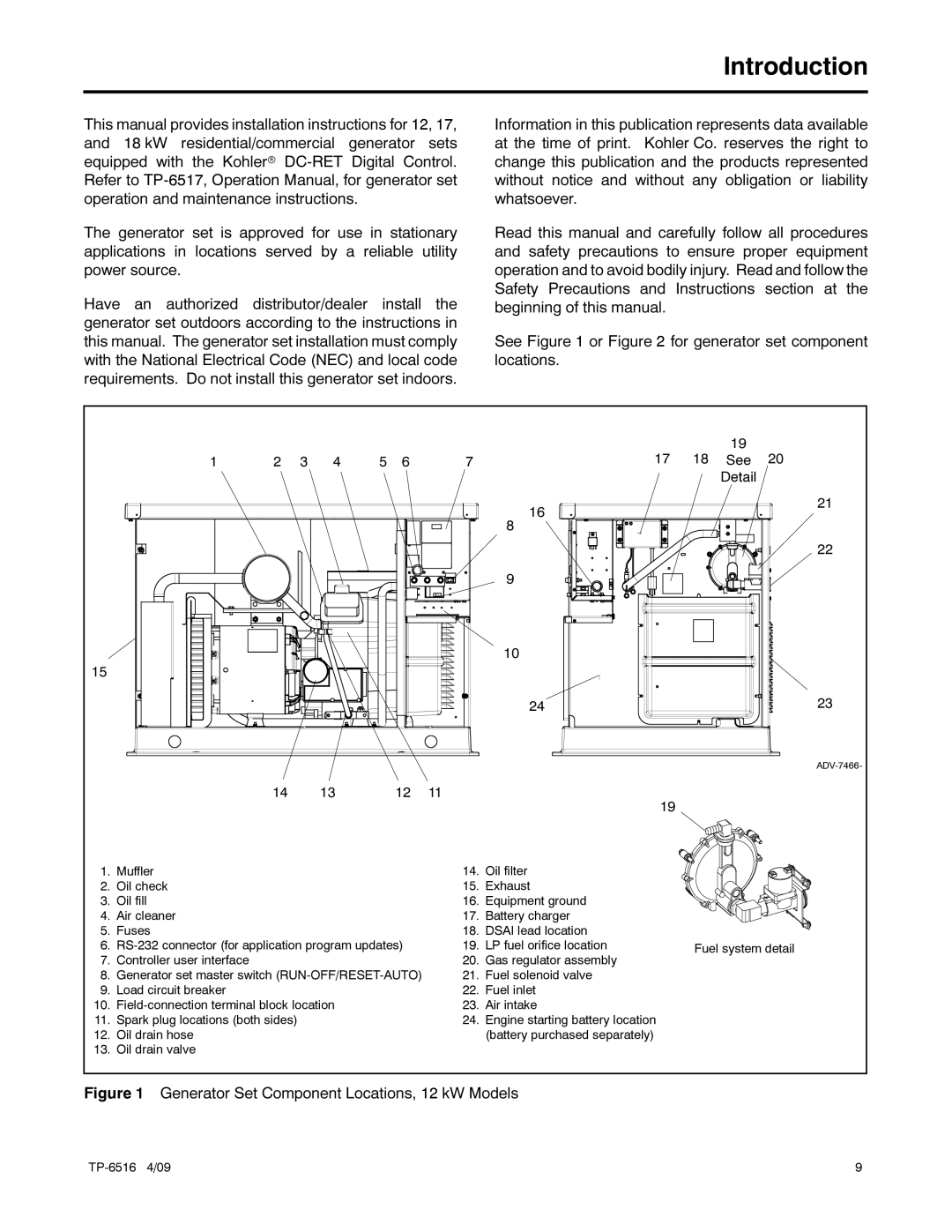
See Figure 1 or Figure 2 for generator set component locations.
|
|
|
| 19 |
1 | 2 3 4 | 5 6 | 7 | 17 18 See 20 |
| Detail |
16 | 21 |
| |
8 |
|
| 22 |
9 |
|
10
15 |
|
|
|
|
|
|
|
|
|
|
| 24 | 23 |
|
|
|
|
|
| |
| 14 | 13 | 12 | 11 |
|
|
|
|
|
|
|
| 19 |
1. | Muffler |
|
| 14. | Oil filter |
|
2. | Oil check |
|
| 15. | Exhaust |
|
3. | Oil fill |
|
| 16. | Equipment ground |
|
4. | Air cleaner |
|
| 17. | Battery charger |
|
5. | Fuses |
|
| 18. | DSAI lead location |
|
6. | 19. | LP fuel orifice location | Fuel system detail | |||
|
|
|
|
|
| |
7. | Controller user interface |
|
| 20. | Gas regulator assembly |
|
8. | Generator set master switch | 21. | Fuel solenoid valve |
| ||
9. | Load circuit breaker |
|
| 22. | Fuel inlet |
|
10. |
| 23. | Air intake |
| ||
11. | Spark plug locations (both sides) |
|
| 24. | Engine starting battery location |
|
12. | Oil drain hose |
|
|
| (battery purchased separately) |
|
13. | Oil drain valve |
|
|
|
|
|
Figure 1 Generator Set Component Locations, 12 kW Models
| 9 |