Section 1 Installation
1.1 General
Have an authorized distributor/dealer install the generator set outdoors according to the instructions in this manual. The generator set installation must comply with the National Electrical Code (NEC) and local code requirements. Do not install this generator set indoors.
Use the generator set and transfer switch dimension drawings and wiring diagrams for installation.
1.2 Lifting
WARNING
Unbalanced weight.
Improper lifting can cause severe injury or death and equipment damage.
Do not use lifting eyes.
Lift the generator set using lifting bars inserted through the lifting holes on the skid.
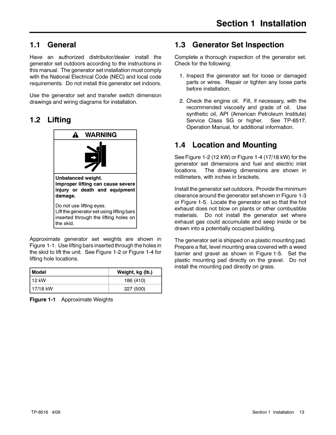
Approximate generator set weights are shown in Figure
Model | Weight, kg (lb.) |
|
|
12 kW | 186 (410) |
|
|
17/18 kW | 227 (500) |
|
|
Figure 1-1 Approximate Weights
1.3 Generator Set Inspection
Complete a thorough inspection of the generator set. Check for the following:
1.Inspect the generator set for loose or damaged parts or wires. Repair or tighten any loose parts before installation.
2.Check the engine oil. Fill, if necessary, with the recommended viscosity and grade of oil. Use synthetic oil, API (American Petroleum Institute) Service Class SG or higher. See
1.4 Location and Mounting
See Figure
Install the generator set outdoors. Provide the minimum clearance around the generator set shown in Figure
The generator set is shipped on a plastic mounting pad. Prepare a flat, level mounting area covered with a weed barrier and gravel as shown in Figure
Section 1 Installation 13 |
