1
2 ![]()
3
12 kW |
1 | 2 | 3 |
17/18 kW | |
|
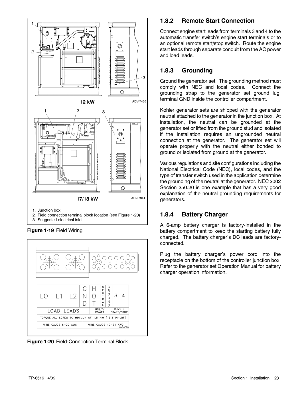
1.Junction box
2.Field connection terminal block location (see Figure
3.Suggested electrical inlet
Figure | Field Wiring |
Figure | |
|
|
1.8.2Remote Start Connection
Connect engine start leads from terminals 3 and 4 to the automatic transfer switch’s engine start terminals or to an optional remote start/stop switch. Route the engine start leads through separate conduit from the AC power and load leads.
1.8.3Grounding
Ground the generator set. The grounding method must comply with NEC and local codes. Connect the grounding strap to the generator set ground lug, terminal GND inside the controller compartment.
Kohler generator sets are shipped with the generator neutral attached to the generator in the junction box. At installation, the neutral can be grounded at the generator set or lifted from the ground stud and isolated if the installation requires an ungrounded neutral connection at the generator. The generator set will operate properly with the neutral either bonded to ground or isolated from ground at the generator.
Various regulations and site configurations including the National Electrical Code (NEC), local codes, and the type of transfer switch used in the application determine the grounding of the neutral at the generator. NEC 2002 Section 250.20 is one example that has a very good explanation of the neutral grounding requirements for generators.
1.8.4Battery Charger
A
Plug the battery charger’s power cord into the receptacle on the bottom of the controller junction box. Refer to the generator set Operation Manual for battery charger operation information.
Section 1 Installation 23