1.4.1Exhaust Requirements
![]() WARNING
WARNING
Carbon monoxide.
Can cause severe nausea, fainting, or death.
The exhaust system must be leakproof and routinely inspected.
1
2
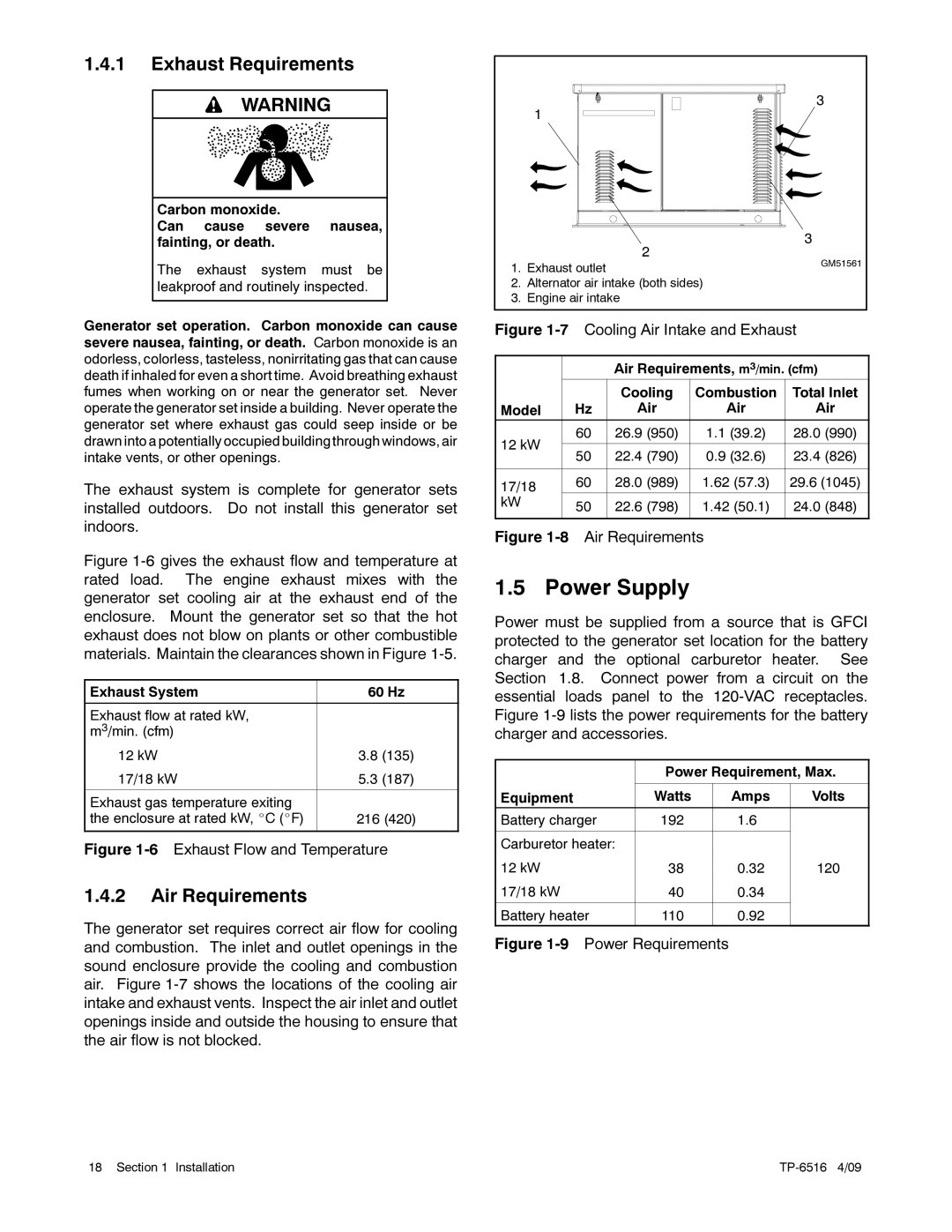
1.Exhaust outlet
2.Alternator air intake (both sides)
3.Engine air intake
3
3
GM51561
Generator set operation. Carbon monoxide can cause severe nausea, fainting, or death. Carbon monoxide is an odorless, colorless, tasteless, nonirritating gas that can cause death if inhaled for even a short time. Avoid breathing exhaust fumes when working on or near the generator set. Never operate the generator set inside a building. Never operate the generator set where exhaust gas could seep inside or be drawn into a potentially occupied building through windows, air intake vents, or other openings.
The exhaust system is complete for generator sets installed outdoors. Do not install this generator set indoors.
Figure 1-6 gives the exhaust flow and temperature at rated load. The engine exhaust mixes with the generator set cooling air at the exhaust end of the enclosure. Mount the generator set so that the hot exhaust does not blow on plants or other combustible materials. Maintain the clearances shown in Figure 1-5.
Exhaust System | 60 Hz |
|
|
Exhaust flow at rated kW, |
|
m3/min. (cfm) |
|
12 kW | 3.8 (135) |
17/18 kW | 5.3 (187) |
|
|
Exhaust gas temperature exiting |
|
the enclosure at rated kW, _C (_F) | 216 (420) |
|
|
Figure 1-6 Exhaust Flow and Temperature
1.4.2Air Requirements
The generator set requires correct air flow for cooling and combustion. The inlet and outlet openings in the sound enclosure provide the cooling and combustion air. Figure
Figure 1-7 Cooling Air Intake and Exhaust
|
| Air Requirements, m3/min. (cfm) | |||
|
| Cooling | Combustion | Total Inlet | |
Model | Hz | Air | Air | Air | |
12 kW | 60 | 26.9 (950) | 1.1 (39.2) | 28.0 (990) | |
|
|
|
| ||
50 | 22.4 (790) | 0.9 (32.6) | 23.4 (826) | ||
| |||||
|
|
|
|
| |
17/18 | 60 | 28.0 (989) | 1.62 (57.3) | 29.6 (1045) | |
|
|
|
| ||
kW | 50 | 22.6 (798) | 1.42 (50.1) | 24.0 (848) | |
| |||||
|
|
|
|
| |
Figure 1-8 Air Requirements
1.5 Power Supply
Power must be supplied from a source that is GFCI protected to the generator set location for the battery charger and the optional carburetor heater. See Section 1.8. Connect power from a circuit on the essential loads panel to the
| Power Requirement, Max. | ||
|
|
|
|
Equipment | Watts | Amps | Volts |
Battery charger | 192 | 1.6 |
|
|
|
|
|
Carburetor heater: |
|
|
|
12 kW | 38 | 0.32 | 120 |
17/18 kW | 40 | 0.34 |
|
|
|
|
|
Battery heater | 110 | 0.92 |
|
|
|
|
|
Figure 1-9 Power Requirements
18 Section 1 Installation |
|