Your Universal Room Controller
|
| Table 1: |
|
|
|
# | Feature | Function |
1 | Mounting holes (2) | For fastening the controller in place |
2 | Faceplate Attachment Holes | For attaching the faceplate to the controller1 |
3 | IR IN Receiver | Accepts IR remote commands (for the |
4 | Configurable Control | Control the room and the A/V equipment (eight buttons) |
| Buttons (Macro Buttons) |
|
5 | RELAY2 | Connect each relay to a room item (such as lighting, screen |
6 | RELAY1 | settings, blinds, and so on)2 |
7 | Connect to the | |
| Connector | PC |
8 | Connect to the | |
| Connector (1 and 2) | other Serial Controller |
9 | IR OUT1 PIN |
|
| GND PIN | Control up to 4 machines via IR Emitters |
| IR OUT2 PIN |
|
10 | GND PIN | Connects |
11 | +12VDC IN PIN | Connects (+) to the connector for powering the unit |
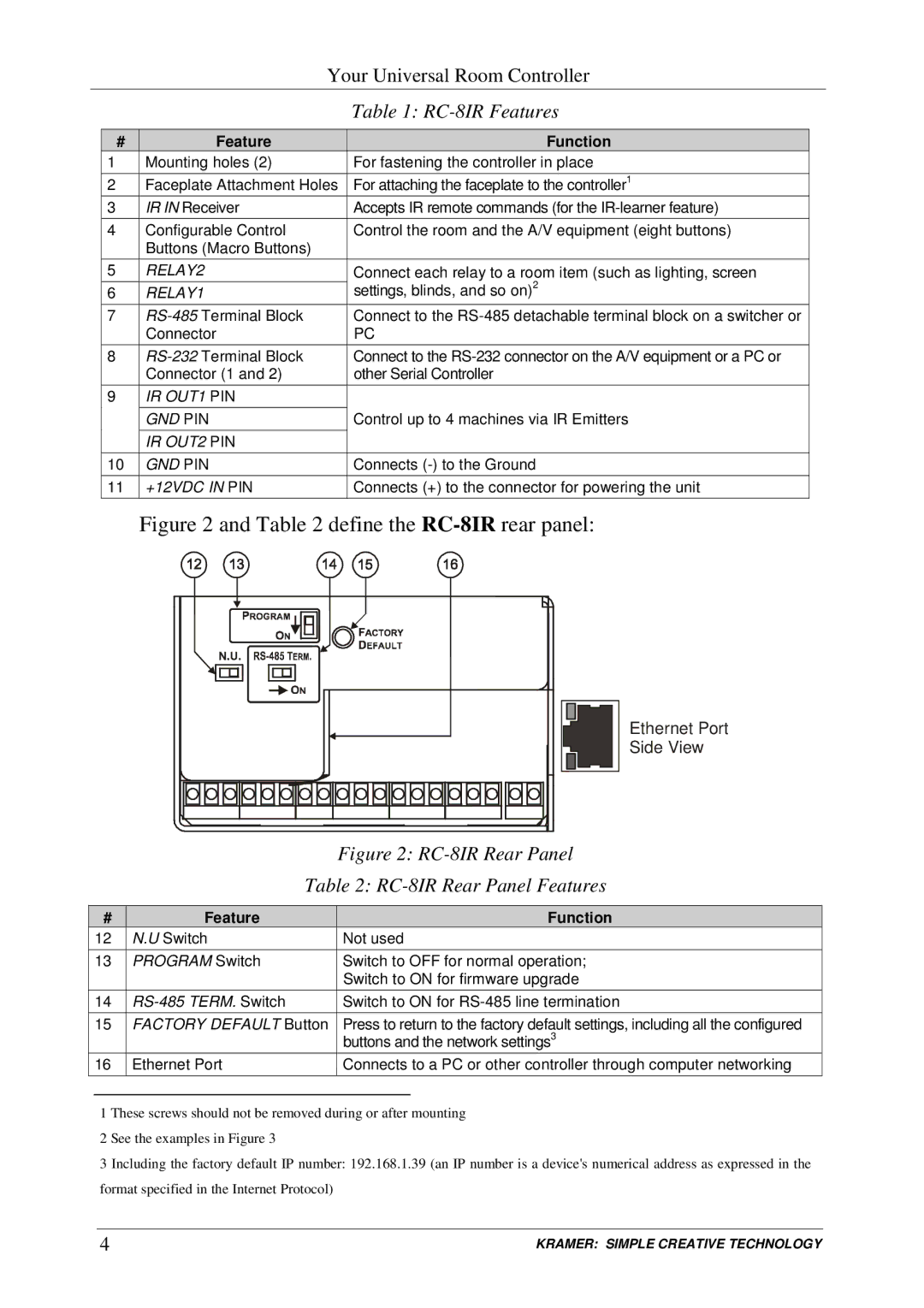
Figure 2 and Table 2 define the RC-8IR rear panel:
Ethernet Port
Side View
|
| Figure 2: |
| Table 2: | |
|
|
|
# | Feature | Function |
12 | N.U Switch | Not used |
13 | PROGRAM Switch | Switch to OFF for normal operation; |
|
| Switch to ON for firmware upgrade |
14 | Switch to ON for | |
15 | FACTORY DEFAULT Button | Press to return to the factory default settings, including all the configured |
|
| buttons and the network settings3 |
16 | Ethernet Port | Connects to a PC or other controller through computer networking |
1 These screws should not be removed during or after mounting 2 See the examples in Figure 3
3 Including the factory default IP number: 192.168.1.39 (an IP number is a device©s numerical address as expressed in the format specified in the Internet Protocol)
4 | KRAMER: SIMPLE CREATIVE TECHNOLOGY |