Page 8 | LAARS HEATING SYSTEMS |
|
|
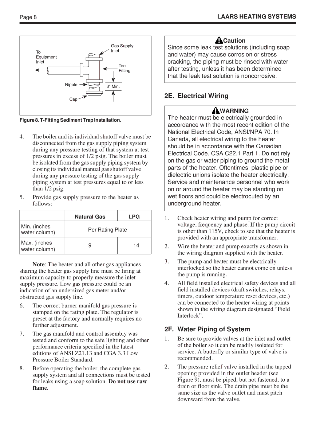
Figure 8. T-Fitting Sediment Trap Installation.
4.The boiler and its individual shutoff valve must be disconnected from the gas supply piping system during any pressure testing of that system at test pressures in excess of 1/2 psig. The boiler must be isolated from the gas supply piping system by closing its individual manual gas shutoff valve during any pressure testing of the gas supply piping system at test pressures equal to or less than 1/2 psig.
5.Provide gas supply pressure to the heater as follows:
| Natural Gas |
| LPG |
|
|
|
|
Min. (inches | Per Rating Plate |
| |
water column) |
| ||
|
|
| |
|
|
|
|
Max. (inches | 9 |
| 14 |
water column) |
| ||
|
|
| |
|
|
|
|
Note: The heater and all other gas appliances sharing the heater gas supply line must be firing at maximum capacity to properly measure the inlet supply pressure. Low gas pressure could be an indication of an undersized gas meter and/or obstructed gas supply line.
6.The correct burner manifold gas pressure is stamped on the rating plate. The regulator is preset at the factory and normally requires no further adjustment.
7.The gas manifold and control assembly was tested and conform to the safe lighting and other performance criteria specified in the latest editions of ANSI Z21.13 and CGA 3.3 Low Pressure Boiler Standard.
8.Before operating the boiler, the complete gas supply system and all connections must be tested for leaks using a soap solution. Do not use raw flame.
![]()
![]() Caution
Caution
Since some leak test solutions (including soap and water) may cause corrosion or stress cracking, the piping must be rinsed with water after testing, unless it has been determined that the leak test solution is noncorrosive.
2E. Electrical Wiring
![]()
![]() WARNING
WARNING
The heater must be electrically grounded in accordance with the most recent edition of the National Electrical Code, ANSI/NPA 70. In Canada, all electrical wiring to the heater should be in accordance with the Canadian Electrical Code, CSA C22.1 Part 1. Do not rely on the gas or water piping to ground the metal parts of the heater. Oftentimes, plastic pipe or dielectric unions isolate the heater electrically. Service and maintenance personnel who work on or around the heater may be standing on wet floors and could be electrocuted by an underground heater.
1.Check heater wiring and pump for correct voltage, frequency and phase. If the pump circuit is other than 115V, check to see that the heater is provided with an appropriate transformer.
2.Wire the heater and pump exactly as shown in the wiring diagram supplied with the heater.
3.The pump and heater must be electrically interlocked so the heater cannot come on unless the pump is running.
4.All field installed electrical safety devices and all field installed devices (draft switches, relays, timers, outdoor temperature reset devices, etc.) can be connected to the heater wiring at points shown in the wiring diagram designated “Field Interlock”.
2F. Water Piping of System
1.Be sure to provide valves at the inlet and outlet of the boiler so it can be readily isolated for service. A butterfly or similar type of valve is recommended.
2.The pressure relief valve installed in the tapped opening provided in the outlet header (see Figure 9), must be piped, but not fastened, to a drain or floor sink. The drain pipe must be the same size as the valve outlet and must pitch downward from the valve.