Page 16 | LAARS HEATING SYSTEMS |
|
|
|
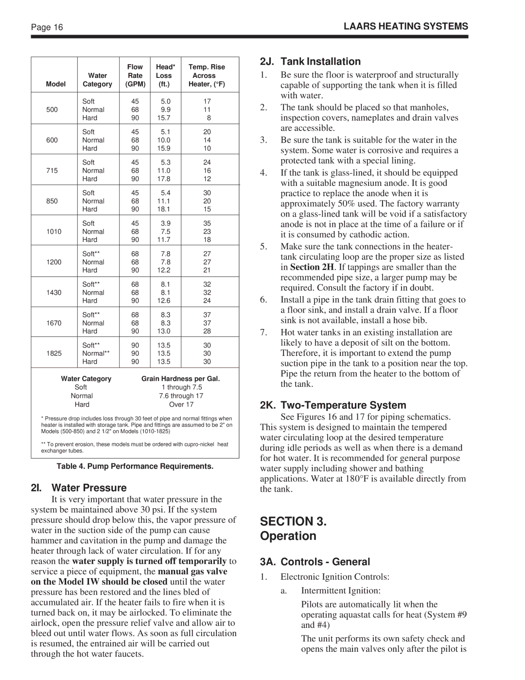
| Flow | Head* | Temp. Rise |
| Water | Rate | Loss | Across |
Model | Category | (GPM) | (ft.) | Heater, (°F) |
|
|
|
|
|
| Soft | 45 | 5.0 | 17 |
500 | Normal | 68 | 9.9 | 11 |
| Hard | 90 | 15.7 | 8 |
|
|
|
|
|
| Soft | 45 | 5.1 | 20 |
600 | Normal | 68 | 10.0 | 14 |
| Hard | 90 | 15.9 | 10 |
|
|
|
|
|
| Soft | 45 | 5.3 | 24 |
715 | Normal | 68 | 11.0 | 16 |
| Hard | 90 | 17.8 | 12 |
|
|
|
|
|
| Soft | 45 | 5.4 | 30 |
850 | Normal | 68 | 11.1 | 20 |
| Hard | 90 | 18.1 | 15 |
|
|
|
|
|
| Soft | 45 | 3.9 | 35 |
1010 | Normal | 68 | 7.5 | 23 |
| Hard | 90 | 11.7 | 18 |
|
|
|
|
|
| Soft** | 68 | 7.8 | 27 |
1200 | Normal | 68 | 7.8 | 27 |
| Hard | 90 | 12.2 | 21 |
|
|
|
|
|
| Soft** | 68 | 8.1 | 32 |
1430 | Normal | 68 | 8.1 | 32 |
| Hard | 90 | 12.6 | 24 |
|
|
|
|
|
| Soft** | 68 | 8.3 | 37 |
1670 | Normal | 68 | 8.3 | 37 |
| Hard | 90 | 13.0 | 28 |
|
|
|
|
|
| Soft** | 90 | 13.5 | 30 |
1825 | Normal** | 90 | 13.5 | 30 |
| Hard | 90 | 13.5 | 30 |
|
|
|
|
|
Water Category | Grain Hardness per Gal. |
Soft | 1 through 7.5 |
Normal | 7.6 through 17 |
Hard | Over 17 |
*Pressure drop includes loss through 30 feet of pipe and normal fittings when heater is installed with storage tank. Pipe and fittings are assumed to be 2" on Models
**To prevent erosion, these models must be ordered with
Table 4. Pump Performance Requirements.
2I. Water Pressure
It is very important that water pressure in the system be maintained above 30 psi. If the system pressure should drop below this, the vapor pressure of water in the suction side of the pump can cause hammer and cavitation in the pump and damage the heater through lack of water circulation. If for any reason the water supply is turned off temporarily to service a piece of equipment, the manual gas valve on the Model IW should be closed until the water pressure has been restored and the lines bled of accumulated air. If the heater fails to fire when it is turned back on, it may be airlocked. To eliminate the airlock, open the pressure relief valve and allow air to bleed out until water flows. As soon as full circulation is resumed, the entrained air will be carried out through the hot water faucets.
2J. Tank Installation
1.Be sure the floor is waterproof and structurally capable of supporting the tank when it is filled with water.
2.The tank should be placed so that manholes, inspection covers, nameplates and drain valves are accessible.
3.Be sure the tank is suitable for the water in the system. Some water is corrosive and requires a protected tank with a special lining.
4.If the tank is
5.Make sure the tank connections in the heater- tank circulating loop are the proper size as listed in Section 2H. If tappings are smaller than the recommended pipe size, a larger pump may be required. Consult the factory if in doubt.
6.Install a pipe in the tank drain fitting that goes to a floor sink, and install a drain valve. If a floor sink is not available, install a hose bib.
7.Hot water tanks in an existing installation are likely to have a deposit of silt on the bottom. Therefore, it is important to extend the pump suction pipe in the tank to a position near the top. Pipe the return from the heater to the bottom of the tank.
2K. Two-Temperature System
See Figures 16 and 17 for piping schematics. This system is designed to maintain the tempered water circulating loop at the desired temperature during idle periods as well as when there is a demand for hot water. It is recommended for general purpose water supply including shower and bathing applications. Water at 180°F is available directly from the tank.
SECTION 3.
Operation
3A. Controls - General
1.Electronic Ignition Controls:
a.Intermittent Ignition:
Pilots are automatically lit when the operating aquastat calls for heat (System #9 and #4)
The unit performs its own safety check and opens the main valves only after the pilot is