Mighty Therm Volume Water Heater | Page 17 |
|
|
|
|
proven to be lit. Whenever the pilot flame is interrupted, the main gas valve closes within
0.8 seconds.
b.Electronically Supervised Standing Pilot System (System #16):
When pilot flame fails, the ignition control module responds in less than 0.8 seconds and provides 100% safety shutdown.
2.Operating Controls:
a.Electrically Operating Controls:
Single,
b.
These valves are furnished in addition to the main electric gas valve when heater is ordered with mechanical modulation. Each valve has a remote capillary bulb immersed in a well at the outlet header to maintain a constant outlet temperature. Consult Table 5 for desired temperature setting.
3.High Limit Controls:
The manual reset high limit switches are provided as standard equipment on all heaters. Automatic reset switches are optionally
Dial No. | 1 | 2 | 3 | 4 | 5 | 6 | 7 | 8 | 9+ |
|
|
|
|
|
|
|
|
|
|
Temp °F | 120 | 128 | 135 | 143 | 150 | 158 | 165 | 173 | 180+ |
|
|
|
|
|
|
|
|
|
|
Table 5.
provided. The temperature sensing bulb of the switch is always located in the heater outlet. Burners will automatically shut down whenever overheating of water occurs.
4.Flow Switch:
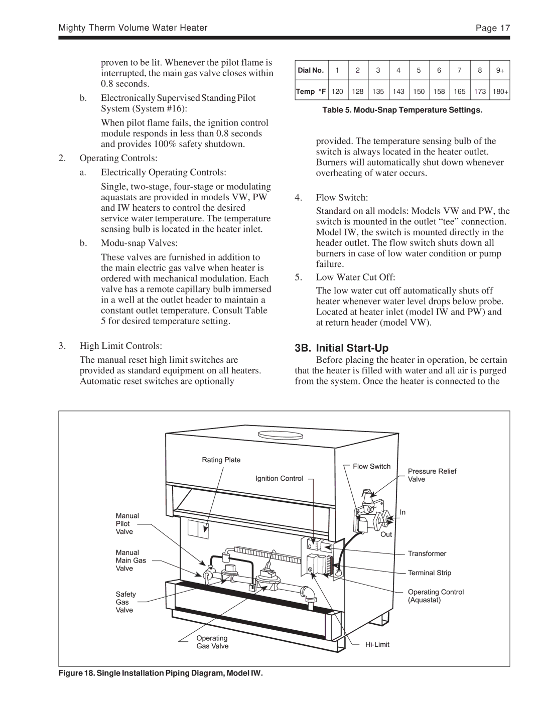
Standard on all models: Models VW and PW, the switch is mounted in the outlet “tee” connection. Model IW, the switch is mounted directly in the header outlet. The flow switch shuts down all burners in case of low water condition or pump failure.
5.Low Water Cut Off:
The low water cut off automatically shuts off heater whenever water level drops below probe. Located at heater inlet (model IW and PW) and at return header (model VW).
3B. Initial Start-Up
Before placing the heater in operation, be certain that the heater is filled with water and all air is purged from the system. Once the heater is connected to the