Page 4 | LAARS HEATING SYSTEMS |
|
|
1C. Flow Requirements
For proper operation, all low volume hot water heaters must have continuous flow through the heat exchanger when firing. The system pump must be capable of developing sufficient pressure to overcome the resistance of the heater plus the entire circulating system at the designed flow rate.
1D. Water Chemistry
Laars equipment is designed for use in a wide variety of water conditions. The water velocity maintained in the heat exchanger tubes is kept high enough to prevent scaling from hard water and low enough to avoid corrosion from soft water. Ninety- five percent of the urban areas in the country have water that is compatible with this equipment, but in some areas a water supply will contain a large quantity of scaling chemicals or the water may be extremely soft and corrosive. In rare situations the water will contain both scaling chemicals and corrosive chemicals such as calcium or sodium chloride. These conditions may be the result of a nearby well or pumping station and the particular condition may not be characteristic of the entire city water system.
If an installer observes damage from these conditions to any water handling equipment in the area, a factory representative should be contacted immediately for assistance in minimizing maintenance costs. If erosion is present, the pump impeller can be replaced to reduce water velocity. If scaling conditions are bad, tube cleaning maintenance schedules can be established to prevent tube
Scaling can be recognized as a layer deposited on the inner walls of the tube which reduces the inner diameter of the tube. Scale can be any color or texture; smooth or rough, granular or amorphous. Signs of erosion are generally pitting, cavitation, ridges and “islands” on the inner walls of the tubes. Since this condition results from extremely soft water sources, or as a result of a water softening program, the internal copper surfaces will be extremely shiny. Other chemicals, such as chlorine or chlorides in the water, will cause dark surfaces of erosion.
In areas where the water supply is extremely corrosive, it is advisable to order the heater with
Damage From Scaling, Corrosion, or Erosion is Not Covered by the Warranty.
SECTION 2.
Installation
2A. Heater Placement
The heater must be placed to provide specific clearances on all sides for maintenance and inspection. There must also be minimum distances maintained from combustible surfaces. These clearances also apply to
Heater should be mounted on a level surface. An integral combustible flooring base is provided as standard equipment on outdoor models. Indoor models can be installed on a combustible floor with a special base assembly which is available from the factory, or with a base that complies with local code requirements. See rating plate for part number of the base assembly.
Do not install a heater on carpeting. Under the National Fuel Gas Code, ANSI
Z223.1, it is permissible to place the heater on floors other than
2B. Installation of Indoor Heaters
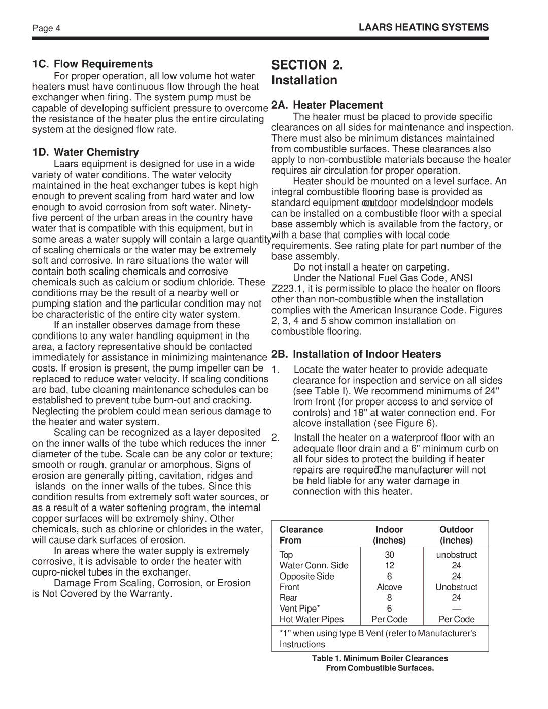
1.Locate the water heater to provide adequate clearance for inspection and service on all sides (see Table I). We recommend minimums of 24" from front (for proper access to and service of controls) and 18" at water connection end. For alcove installation (see Figure 6).
2.Install the heater on a waterproof floor with an adequate floor drain and a 6" minimum curb on all four sides to protect the building if heater repairs are required. The manufacturer will not be held liable for any water damage in connection with this heater.
Clearance | Indoor | Outdoor |
From | (inches) | (inches) |
|
|
|
Top | 30 | unobstruct |
Water Conn. Side | 12 | 24 |
Opposite Side | 6 | 24 |
Front | Alcove | Unobstruct |
Rear | 8 | 24 |
Vent Pipe* | 6 | — |
Hot Water Pipes | Per Code | Per Code |
*1" when using type B Vent (refer to Manufacturer's Instructions
Table 1. Minimum Boiler Clearances
From Combustible Surfaces.