Mighty Therm Volume Water Heater | Page 7 |
|
|
|
|
maintain clearances and prevent physical damage and separation of joints.
4.Avoid ending heater vents near air conditioning or air supply fans. The fans can pick up exhaust flue products from the heater and return them inside the building, creating a possible health hazard. A minimum of 4 feet horizontal distance must be maintained from electrical meters, gas meters, and relief equipment.
5.Always use
6.Avoid oversize vent piping or extremely long runs of the pipe which may cause excessive cooling and condensation. Rule of Thumb: The total length of the vent, including the connector and any offset, should not exceed 15 feet for every inch of vent diameter. Longer total lengths shown in venting tables are based on maximum capacity, not condensation factors.
7.When the installation of a draft fan is necessary in connecting a venting system to a Laars heater, the installation should be engineered by competent personnel following good engineering practices. The draft fan supplier should be consulted for correct size. The installation should be in accordance with the latest edition of ANSI Z223.1 and/or, in Canada,
2C. Installation of Outdoor Heaters
1.Locate the heater to provide the minimum clearances as listed in Table 1, “Placement of Heater”.
2.Do not place the heater in an enclosure or wall recess. Avoid locations where wind deflection off structures might cause down draft. When such wind conditions are possible, place the heater at least three (3) feet from the structures.
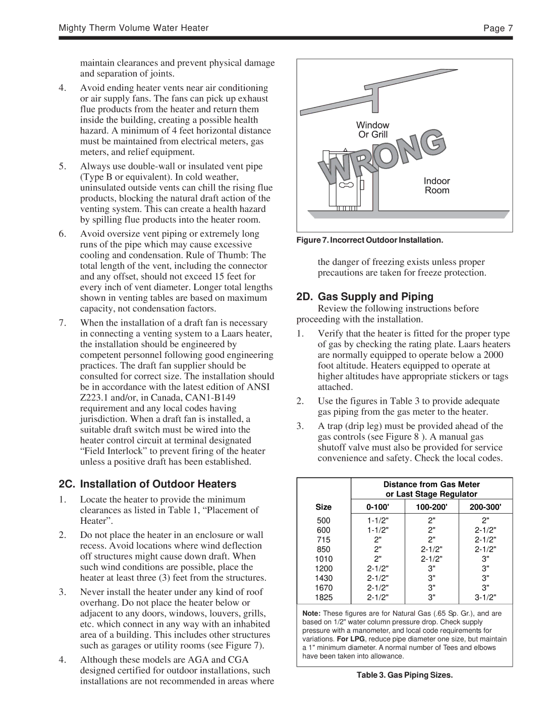
3.Never install the heater under any kind of roof overhang. Do not place the heater below or adjacent to any doors, windows, louvers, grills, etc. which connect in any way with an inhabited area of a building. This includes other structures such as garages or utility rooms (see Figure 7).
4.Although these models are AGA and CGA designed certified for outdoor installations, such installations are not recommended in areas where
Figure 7. Incorrect Outdoor Installation.
the danger of freezing exists unless proper precautions are taken for freeze protection.
2D. Gas Supply and Piping
Review the following instructions before proceeding with the installation.
1.Verify that the heater is fitted for the proper type of gas by checking the rating plate. Laars heaters are normally equipped to operate below a 2000 foot altitude. Heaters equipped to operate at higher altitudes have appropriate stickers or tags attached.
2.Use the figures in Table 3 to provide adequate gas piping from the gas meter to the heater.
3.A trap (drip leg) must be provided ahead of the gas controls (see Figure 8 ). A manual gas shutoff valve must also be provided for service convenience and safety. Check the local codes.
| Distance from Gas Meter | ||
| or Last Stage Regulator | ||
Size | |||
500 | 2" | 2" | |
600 | 2" | ||
715 | 2" | 2" | |
850 | 2" | ||
1010 | 2" | 3" | |
1200 | 3" | 3" | |
1430 | 3" | 3" | |
1670 | 3" | 3" | |
1825 | 3" | ||
|
|
|
|
Note: These figures are for Natural Gas (.65 Sp. Gr.), and are based on 1/2" water column pressure drop. Check supply pressure with a manometer, and local code requirements for variations. For LPG, reduce pipe diameter one size, but maintain a 1" minimum diameter. A normal number of Tees and elbows have been taken into allowance.
Table 3. Gas Piping Sizes.