Mighty Therm Volume Water Heater |
|
|
|
|
|
|
|
|
|
| Page 9 | |||
|
|
|
|
|
|
|
|
|
|
|
|
|
|
|
|
|
|
|
|
|
|
|
|
|
|
|
|
|
|
|
|
|
|
|
|
|
|
|
|
|
|
|
|
|
|
|
|
|
|
|
|
|
|
|
|
|
|
|
|
|
|
|
|
|
|
|
|
|
|
|
|
|
|
|
|
|
|
|
|
|
|
|
|
|
|
|
|
|
|
|
|
|
|
|
|
|
|
|
|
|
|
|
|
|
|
|
|
|
|
|
|
|
|
|
|
|
|
|
|
|
|
|
|
|
|
|
|
|
|
|
|
|
|
|
|
|
|
|
|
|
|
|
|
|
|
|
|
|
|
|
|
|
|
|
|
|
|
|
|
|
|
|
|
|
|
|
|
|
|
|
|
|
|
|
|
|
|
|
|
|
|
|
|
|
|
|
|
|
|
|
|
|
|
|
|
|
|
|
|
|
|
|
|
|
|
|
|
|
|
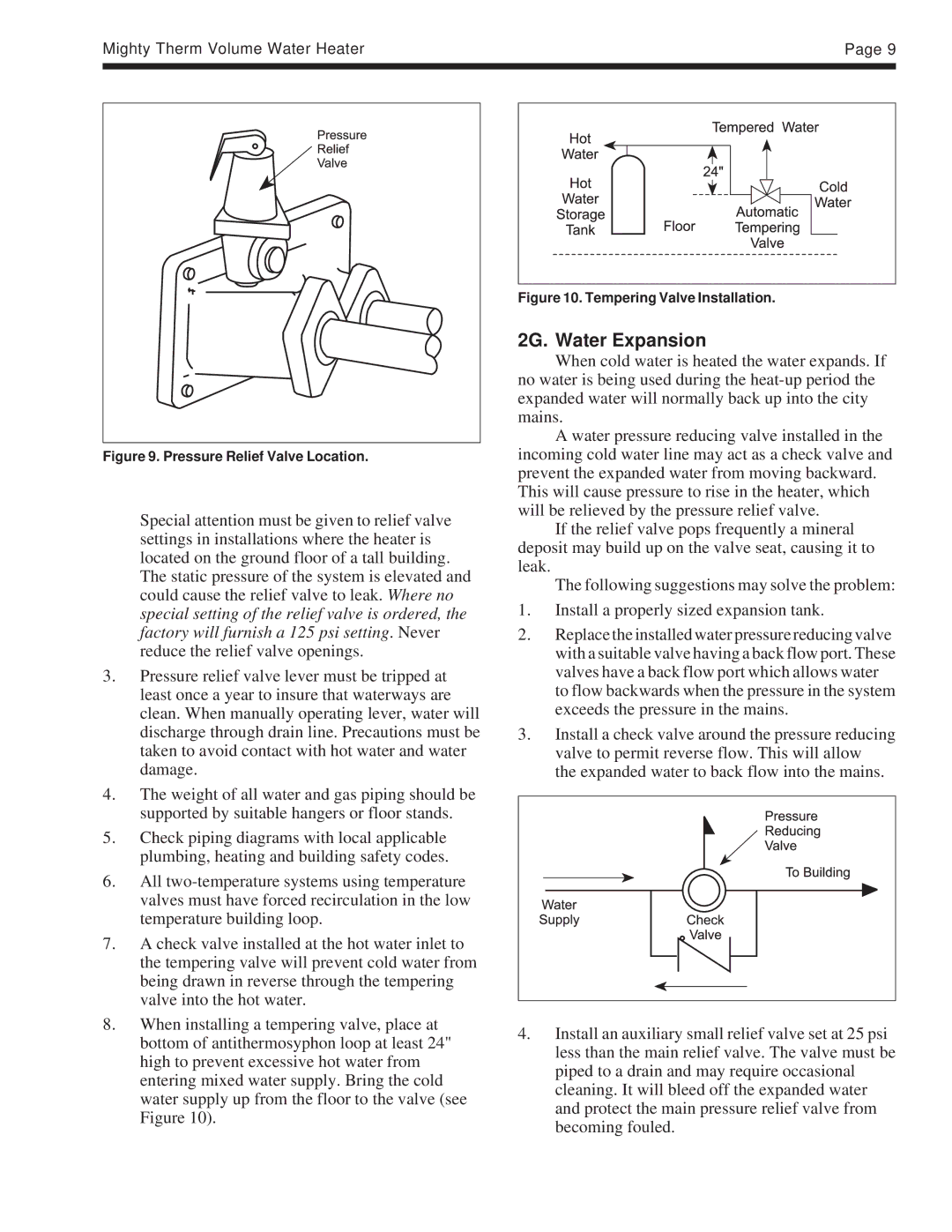
Figure 9. Pressure Relief Valve Location.
Special attention must be given to relief valve settings in installations where the heater is located on the ground floor of a tall building. The static pressure of the system is elevated and could cause the relief valve to leak. Where no special setting of the relief valve is ordered, the factory will furnish a 125 psi setting. Never reduce the relief valve openings.
3.Pressure relief valve lever must be tripped at least once a year to insure that waterways are clean. When manually operating lever, water will discharge through drain line. Precautions must be taken to avoid contact with hot water and water damage.
4.The weight of all water and gas piping should be supported by suitable hangers or floor stands.
5.Check piping diagrams with local applicable plumbing, heating and building safety codes.
6.All
7.A check valve installed at the hot water inlet to the tempering valve will prevent cold water from being drawn in reverse through the tempering valve into the hot water.
8.When installing a tempering valve, place at bottom of antithermosyphon loop at least 24" high to prevent excessive hot water from entering mixed water supply. Bring the cold water supply up from the floor to the valve (see Figure 10).
Figure 10. Tempering Valve Installation.
2G. Water Expansion
When cold water is heated the water expands. If no water is being used during the
A water pressure reducing valve installed in the incoming cold water line may act as a check valve and prevent the expanded water from moving backward. This will cause pressure to rise in the heater, which will be relieved by the pressure relief valve.
If the relief valve pops frequently a mineral deposit may build up on the valve seat, causing it to leak.
The following suggestions may solve the problem:
1.Install a properly sized expansion tank.
2.Replace the installed water pressure reducing valve with a suitable valve having a back flow port. These valves have a back flow port which allows water to flow backwards when the pressure in the system exceeds the pressure in the mains.
3.Install a check valve around the pressure reducing valve to permit reverse flow. This will allow the expanded water to back flow into the mains.
4.Install an auxiliary small relief valve set at 25 psi less than the main relief valve. The valve must be piped to a drain and may require occasional cleaning. It will bleed off the expanded water and protect the main pressure relief valve from becoming fouled.