Table of Contents
Section 1: Assembly &
Land Pride
Pull Type Hitch Assembly (Optional)
Refer to “Torque Values Chart For Common Bolt Size” on page 21 when tightening hardware.
Refer to Figure 1-2 & Figure 1-3:
1.Chock front and back of rollers to prevent unit from shifting. Support 2" square tube frame up so that the top of the clevis plates are level.
2.Remove support stand (#3) and wire snap lock pin (#1A) from the clevis plates (shipping location).
3.The front two holes in hitch frame (#4) should be shipped from the factory attached to the front holes in the clevis plates with hitch pins (#17) and linch pins (#11). If not, make this pin connection now.
4.Rotate hitch frame (#4) down to align rear holes in hitch frame with holes at the back of the clevis plates. Insert
nuts (#16). Draw nuts up snug, do not tighten.
5.Remove 3/4" hex cap screws (#9), 2" spacer (#2) and and 3/8" cap screws (#8) from hitch frame (#4).
IMPORTANT: The tongue (#5) should be as near level as possible when pulling the roller over soil. Before proceeding, determine which hitch assembly below to use that will mount the tongue near level.
•Use hitch assembly in Figure
•Use hitch assembly in Figure
6.Attach tongue (#5) to
a.Remove bolts (#8) from back of tongue (#5).
b.Attach middle of tongue to hitch (#2) with two
c.Attach back of tongue with two
7.Tighten flange lock nuts (#14, #15 & #16) to the correct torques.
NOTE: See Figure
8.Remove wire snap lock pin (#1B). Reorient ball hitch (#6) and clevis hitch (#7) with preferred hitch facing forward and then reattach hitch to tongue (#5) with wire snap lock pins (#1A & 1B).
9.Attach support stand (#3) to wire snap lock pin (#1A). When not in use, rotate stand up and secure in place with second wire snap lock pin (#1B).
10.If clevis hitch (#7) is facing forward, insert 3/4" hitch pin (#12) and secure with hair pin cotter (#13). If ball hitch (#6) is facing forward, store hitch pin and hair pin cotter in a safe location of your choosing.
Roller Scraper Assembly
Refer to “Torque Values Chart For Common Bolt Size” on page 21 when tightening hardware.
Refer to Figure 1-4 on page 9:
1.Attach roller scraper assembly to the Seed Bed Roller frame with
2.Tighten nuts to the correct torque.
3.Some adjustment to the scraper teeth can be made by loosening the nuts on scraper (#1). Retighten nuts after adjustment has been made. See “Scraper Bar Adjustment” on page 11 for detailed instructions.
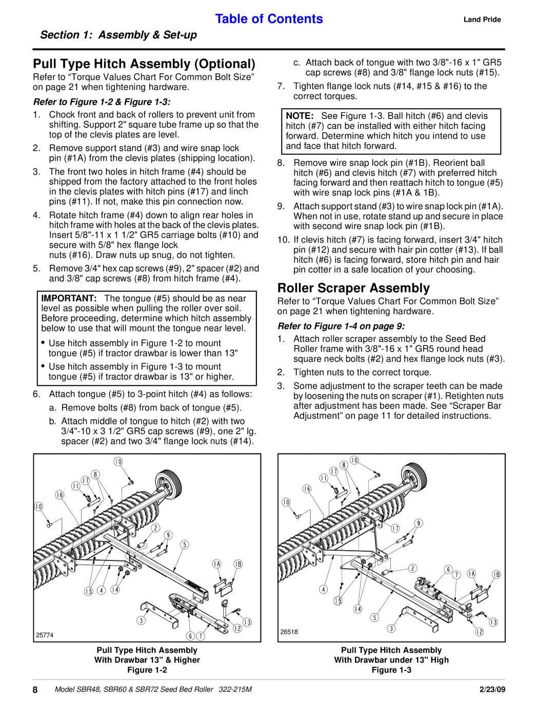
25774 |
26518 |
Pull Type Hitch Assembly | Pull Type Hitch Assembly |
With Drawbar 13" & Higher | With Drawbar under 13" High |
Figure | Figure |
|
|
8 | Model SBR48, SBR60 & SBR72 Seed Bed Roller | 2/23/09 |