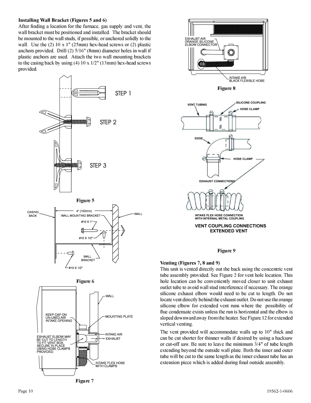
Installing Wall Bracket (Figures 5 and 6)
After finding a location for the furnace, gas supply and vent, the wall bracket must be positioned and installed. The bracket should be mounted to the wall studs, if possible, or anchored solidly to the wall. Use the (2) 10 x 1" (25mm)
| Figure 5 |
| |
CASING | 4" (102mm) | WALL | |
WALL MOUNTING BRACKET | |||
BACK | |||
| |||
| #10 X 1" |
|
#10 X 1/2"
WALL
BRACKET
#10 X 1/2"
Figure 6
EXHAUST AIR
ORANGE SILICONE
ELBOW CONNECTOR
| INTAKE AIR |
| BLACK FLEXIBLE HOSE |
| Figure 8 |
VENT TUBING | SILICONE COUPLING |
| |
| HOSE CLAMP |
EDGE
HOSE CLAMP
EXHAUST CONNECTIONS
INTAKE FLEX HOSE CONNECTION
WITH INTERNAL METAL COUPLING
VENT COUPLING CONNECTIONS
EXTENDED VENT
Figure 9
Venting (Figures 7, 8 and 9)
This unit is vented directly out the back using the concentric vent tube assembly provided. See Figure 2 for vent hole location. This hole location can be conveniently moved closer to unit exhaust outlet tube to avoid wall stud interference if necessary. The orange silicone exhaust elbow would need to be cut to length. Do not
KEEP CAP ON
INTAKE OPENING
EXHAUST ELBOW MAY BE CUT TO LENGTH TO FIT VENT BOX. SECURE IN PLACE USING HOSE CLAMPS PROVIDED.
WALL
MOUNTING PLATE
INTAKE AIR
EXHAUST
INTAKE![]()
![]() FLEX HOSE WITH CLAMPS
FLEX HOSE WITH CLAMPS
locate vent directly behind the exhaust outlet. Do not use the orange silicone elbow for extended vent runs where the possibility of flue condensate exists unless the run is horizontal and the elbow is sloped downward away from the heater. See Figure 12 for extended vertical venting.
The vent provided will accommodate walls up to 10" thick and can be cut shorter for thinner walls if desired by using a hacksaw or
Figure 7
Page 10 |