WIRING
OPTIONAL WALL MOUNT THERMOSTAT
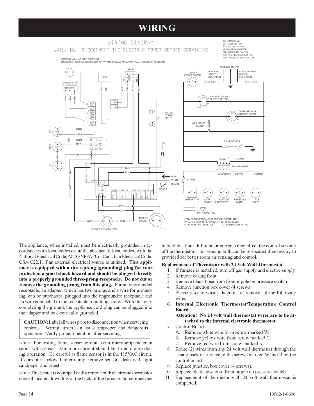
DISCONNECT INTEGRAL THERMOSTAT "R", "W", AND "C" LEADS AND ATTACH WALL THERMOSTAT AS SHOWN
XFMR
WR
|
|
|
|
| GV | V |
|
| V | |
THERMOSTAT |
|
|
|
| 24 |
|
| 115 | ||
|
|
|
|
|
|
|
| |||
ELECTRONIC |
|
| BRN | BRN | GRY | GRY | WHT | BLK | ||
INTEGRAL |
|
| ||||||||
|
|
|
|
| ||||||
WHT | YEL | RED |
|
|
|
|
|
|
|
|
|
|
|
|
|
|
|
|
|
| RED LED |
|
|
|
|
|
|
|
|
|
| STATUS |
|
|
|
|
|
|
|
|
|
| LIGHT |
PS |
| ORG |
|
|
|
|
|
|
|
|
| ORG |
|
|
|
|
|
|
|
| |
|
|
|
|
|
|
|
|
|
| |
|
| GRN | 9 | 6 | 3 |
|
|
|
| IGN |
ROS |
| RED | 8 | 5 | 2 |
|
|
|
| |
|
|
|
|
|
| |||||
|
| 7 | 4 | 1 |
|
|
|
|
| |
|
|
|
|
|
|
|
| |||
RED |
| RED |
|
|
|
|
|
|
|
|
|
|
|
|
|
|
|
|
|
| |
LS |
|
|
|
|
|
|
| BLU |
|
|
| YEL |
|
|
|
|
|
|
|
| |
|
|
|
|
|
|
| BLU |
|
| |
|
|
|
|
|
|
|
|
|
| GND |
|
|
|
|
|
|
|
|
|
| WHITE |
|
|
|
| 6 | 3 |
|
|
|
| BLACK |
|
|
|
|
|
|
|
| ON/OFF | ||
|
|
|
| 5 | 2 |
|
|
|
| |
|
|
|
|
|
|
|
|
| ||
| FS |
|
| 4 | 1 |
|
|
|
|
|
|
|
|
|
|
|
| PUR |
|
|
|
|
|
|
|
|
|
| PUR |
|
|
|
|
|
|
|
|
|
|
|
|
| INDUCER |
|
|
| WHT |
|
|
| BLK |
|
| BLOWER |
CIRCULATING AIR BLOWER
|
|
|
|
| GV = GAS VALVE | ||||||||||||
|
|
|
|
| LS = LIMIT SWITCH | ||||||||||||
|
|
|
|
| FS = FLAME SENSOR | ||||||||||||
|
|
|
|
| XFMR = TRANSFORMER | ||||||||||||
|
|
|
|
| PS = PRESSURE SWITCH | ||||||||||||
|
|
|
|
| IGN = HOT SURFACE IGNITOR | ||||||||||||
|
|
|
|
| ROS = ROLLOUT LIMIT SWITCH | ||||||||||||
|
|
|
| CORDSET 115 VAC | |||||||||||||
ON/OFF | BLACK HOT |
|
|
|
|
|
|
|
|
|
|
| BLACK NEUTRAL | ||||
SMOOTH |
|
|
|
|
|
|
|
|
|
|
| RIBBED | |||||
POWER SWITCH |
|
|
|
|
|
|
|
|
|
|
| ||||||
INSULATION |
|
|
|
|
|
|
|
|
|
|
| INSULATION | |||||
|
|
|
|
|
|
|
|
|
|
|
|
|
| ||||
|
|
|
|
|
|
|
|
|
|
|
|
|
|
|
|
|
|
|
|
|
|
|
|
|
|
|
|
|
|
|
|
|
|
|
|
|
|
|
|
|
|
|
|
|
|
|
|
|
|
|
|
|
|
|
|
|
|
|
|
|
|
|
|
|
|
|
|
|
|
|
|
|
|
|
|
|
|
|
|
|
|
|
|
|
|
|
|
|
|
CIRCULATING AIR
BLOWER MOTOR
COMBUSTION AIR
INDUCER MOTOR
HOT SURFACE
IGNITOR
FLAME SENSOR
|
| PRIMARY | 115 VAC |
|
|
|
| TRANSFORMER |
|
|
| SECONDARY | 24 VAC | COMMON |
3A FUSE |
|
|
|
|
THERMOSTAT | LIMIT | ROLLOUT | PRESSURE | GAS |
| SWITCH | LIMIT SWITCH | SWITCH | VALVE |
115VAC
24VOLT FIELD INSTALLED
IF ANY OF THE ORIGINAL WIRE AS SUPPLIED WITH THE
APPLIANCE MUST BE REPLACED, IT MUST BE REPLACED
WITH A WIRE OF AT LEAST 105 | ° C TEMPERATURE RATING. |
The appliance, when installed, must be electrically grounded in ac- cordance with local codes or, in the absence of local codes, with the National Electrical Code,ANSI/NFPA70 or Canadian Electrical Code, CSA C22.1, if an external electrical source is utilized. This appli- ance is equipped with a
CAUTION: Label all wires prior to disconnection when servicing controls. Wiring errors can cause improper and dangerous operation. Verify proper operation after servicing.
Note: For testing flame sensor circuit use a
Note: This heater is equipped with a remote bulb electronic thermistor control located down low at the back of the furnace. Sometimes due
to field locations different air currents may effect the control sensing of the thermistor. This sensing bulb can be
Replacement of Thermistor with 24 Volt Wall Thermostat
1.If furnace is installed, turn off gas supply and electric supply.
2.Remove casing front.
3.Remove black hose from front nipple on pressure switch.
4.Remove junction box cover (4 screws).
5.Please refer to wiring diagram for removal of the following wires.
6.Internal Electronic Thermostat/Temperature Control Board
Attention! No 24 volt wall thermostat wires are to be at- tached to the internal electronic thermostat.
7.Control Board
A.Remove white wire form screw marked W.
B.Remove yellow wire from screw marked C.
C.Remove red wire from screw marked R.
8.Route (2) wires from any 24 volt wall thermostat through the casing back of furnace to the screws marked W and R on the control board.
9.Replace junction box cover (4 screws).
10.Replace black hose onto front nipple on pressure switch.
11.Replacement of thermistor with 24 volt wall thermostat is completed.
Page 14 |