CLEARANCES
1.Pick a location on a wall with a clear space of 36" (91.4cm) high by 43" (109cm) wide in the room. In selecting a location for installation, it is necessary to provide adequate accessibility clearances for servicing and proper installation. Be sure to locate the unit close enough to a 115 VAC wall receptacle to properly power appliance.
2.Unit is supported by a wall bracket secured to the wall.
3.When facing the front of the furnace the minimum clearances from casing to combustible construction are 10" (254mm) on top, 3" (76mm) on each side, recommend 18" (457mm) on right side for servicing and 0" (0mm) from the floor and 0" (0mm) to rear wall.
4.The black flocked exhaust pipe, contained in
5.The minimum distance from the center of the vent cap to the nearest outside corner or obstruction is 12" (305mm).
6.The minimum wall depth is 2" (51mm) and the maximum is 10" (254mm) [or 32"(813mm) using the extended vent terminal kit accessory]. The use of vent tubes not supplied by the manufacturer may result in unsatisfactory performance.
The vent terminal of a direct vent appliance, with an input of 50,000 BTU (14.6KW) per hour or less shall be located at least 9" (229mm) from any opening through which flue gases could enter a building.
The bottom of the exhaust vent terminal and the air intake shall be located at least 12" (305mm) above grade and must be vented outside.
WARNING: The nearest point of the vent cap should be a minimum horizontal distant of six (6) feet (1.83m) from any pressure regulator. In case of regulator malfunction, the six (6) feet (1.83m) distance will reduce the chance of gas entering the vent cap.
Installation on Rugs and Tile
If this appliance is to be installed directly on carpeting, tile, or other combustible material, other than wood flooring, the appliance shall be installed on a metal or wood panel extending the full width and depth of the appliance.
The base referred to above does not mean the
FURNACE INSTALLATION
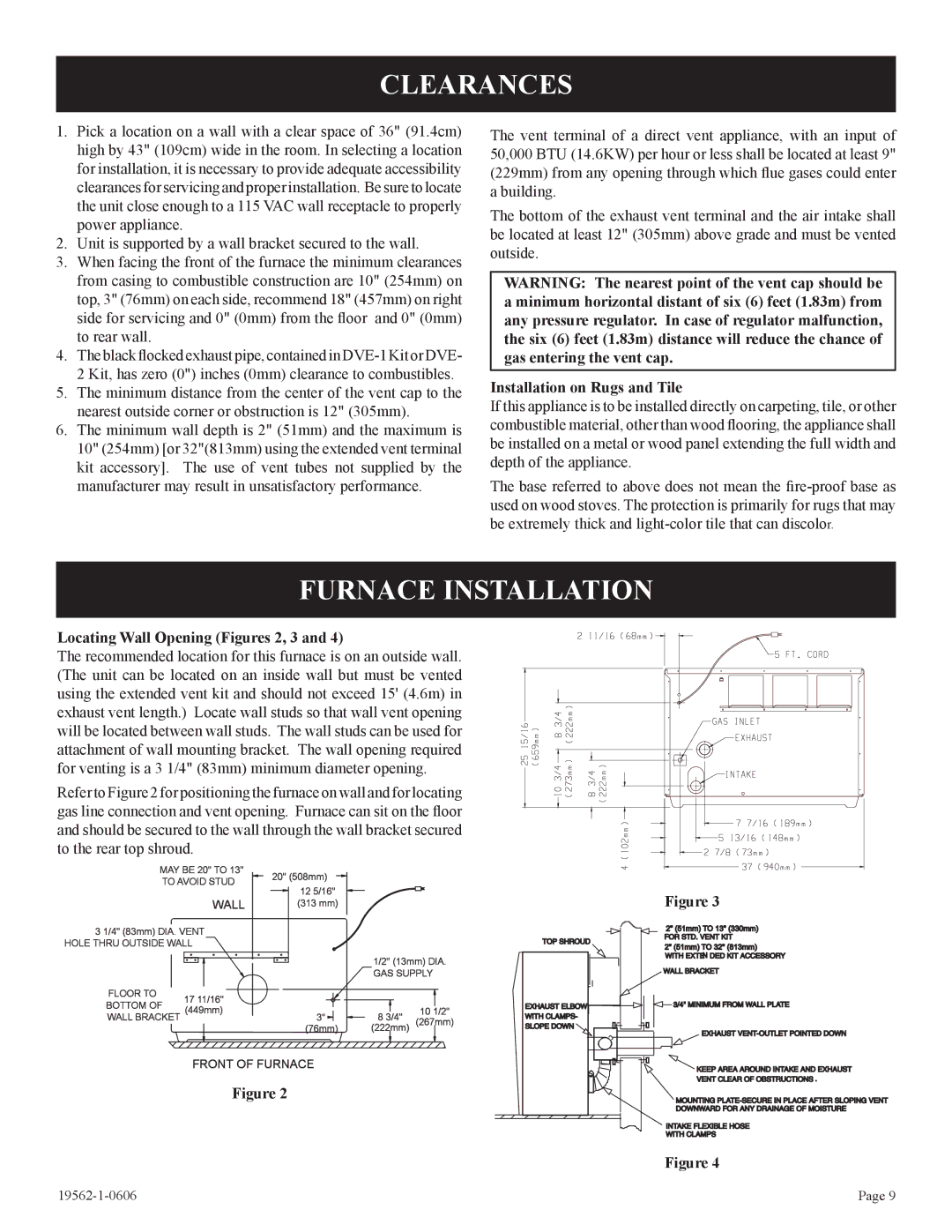
Locating Wall Opening (Figures 2, 3 and 4)
The recommended location for this furnace is on an outside wall. (The unit can be located on an inside wall but must be vented using the extended vent kit and should not exceed 15' (4.6m) in exhaust vent length.) Locate wall studs so that wall vent opening will be located between wall studs. The wall studs can be used for attachment of wall mounting bracket. The wall opening required for venting is a 3 1/4" (83mm) minimum diameter opening.
Refer to Figure 2 for positioning the furnace on wall and for locating gas line connection and vent opening. Furnace can sit on the floor and should be secured to the wall through the wall bracket secured to the rear top shroud.
MAY BE 20" TO 13" | 20" (508mm) | |
TO AVOID STUD | ||
12 5/16" | ||
|
WALL | (313 mm) |
3 1/4" (83mm) DIA. VENT HOLE THRU OUTSIDE WALL
|
|
| 1/2" (13mm) DIA. | |
|
|
| GAS SUPPLY | |
FLOOR TO | 17 11/16" |
|
|
|
BOTTOM OF |
|
|
| |
(449mm) |
| 8 3/4" | 10 1/2" | |
WALL BRACKET | 3" | |||
|
| (76mm) | (222mm) | (267mm) |
FRONT OF FURNACE
Figure 2
Figure 3
2" (51mm) TO 13" (330mm)
2" (51mm) TO 32" (813mm)
Figure 4
Page 9 |