Page 5 | Digital Display Wall Clock Guide |
|
|
Configuring the DDC Series Wall Clock
Setting the DIP Switches - DDC2 / DDC4 Series
DDC2
Remove the four phillips head screws from the left or the right end cap and remove. Slide the lens and circuit board assembly out of the case. Place the lens aside and carefully flip the circuit board assembly over and lay it face down on a clean, smooth work surface. Locate switch S1near the center of the circuit board and set the DIP switches (See figure1below) according to Tables 1, 2 and 3 on the following page for the proper configuration. Slide the lens and circuit board assembly back into the case, replace the end cap and secure with the four phillips head screws.
DDC4
Remove the two phillips head screws from the left or the right end cap and remove. Slide the front panel assembly out of the case. Carefully flip the front panel assembly over and lay it face down on a clean, smooth work surface. Locate switch S1near the center of the circuit board and set the DIP switches (See figure1below) according to Tables 1, 2 and 3 on the following page for the proper configuration. Slide the front panel display back into the case, replace the end cap and secure with the two phillips head screws.
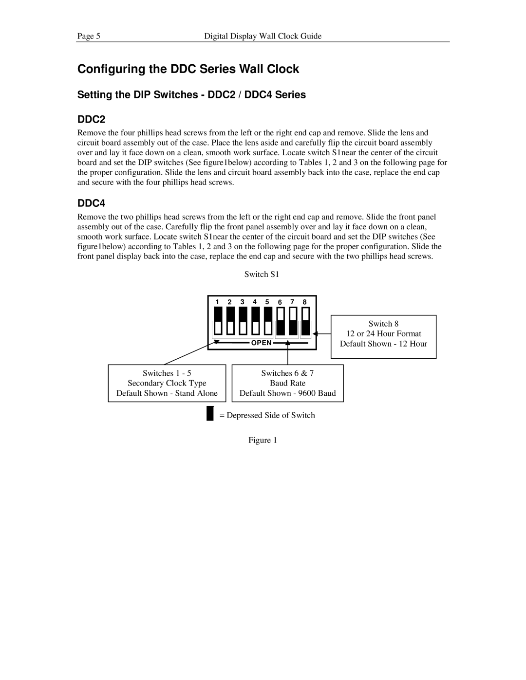
Switch S1
1 | 2 | 3 | 4 | 5 | 6 | 7 | 8 |
![]() OPEN
OPEN![]()
Switch 8
12 or 24 Hour Format
Default Shown - 12 Hour
Switches 1 - 5
Secondary Clock Type
Default Shown - Stand Alone
Switches 6 & 7
Baud Rate
Default Shown - 9600 Baud
=Depressed Side of Switch
Figure 1