Page 27 | Digital Display Wall Clock Guide | DDC2 / |
|
|
|
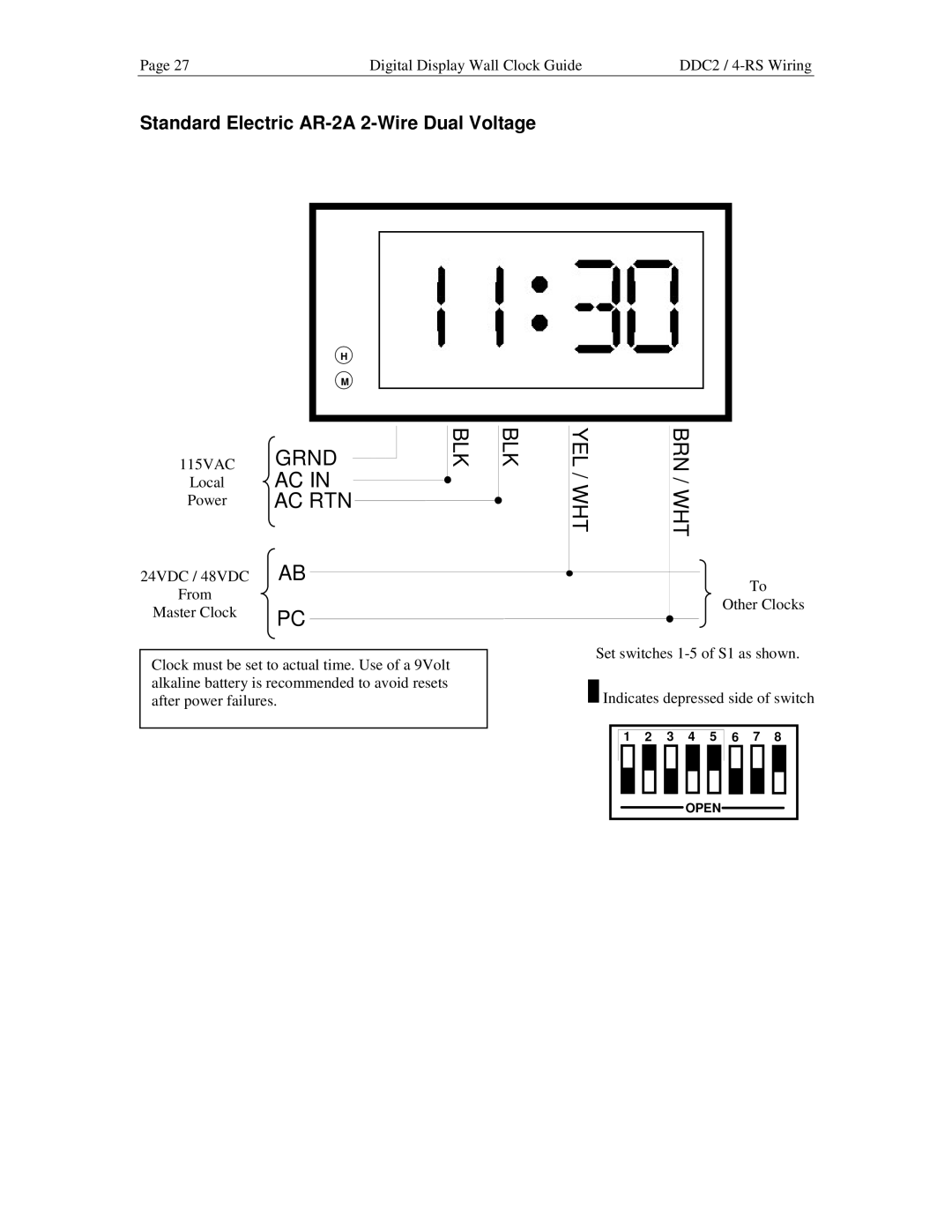
Standard Electric AR-2A 2-Wire Dual Voltage
| H |
|
| M |
|
115VAC | GRND | BLK |
Local | AC IN |
|
Power | AC RTN |
|
24VDC / 48VDC | AB |
|
From |
|
|
Master Clock | PC |
|
Clock must be set to actual time. Use of a 9Volt alkaline battery is recommended to avoid resets after power failures.
BLK | YEL | BRN |
| / WHT | / WHT |
|
|
|
To
Other Clocks
Set switches
![]()
![]() Indicates depressed side of switch
Indicates depressed side of switch
1 | 2 | 3 | 4 | 5 | 6 | 7 | 8 |
OPEN